Preparing your learning space...
100% through CISCO Packet Tracer tutorials
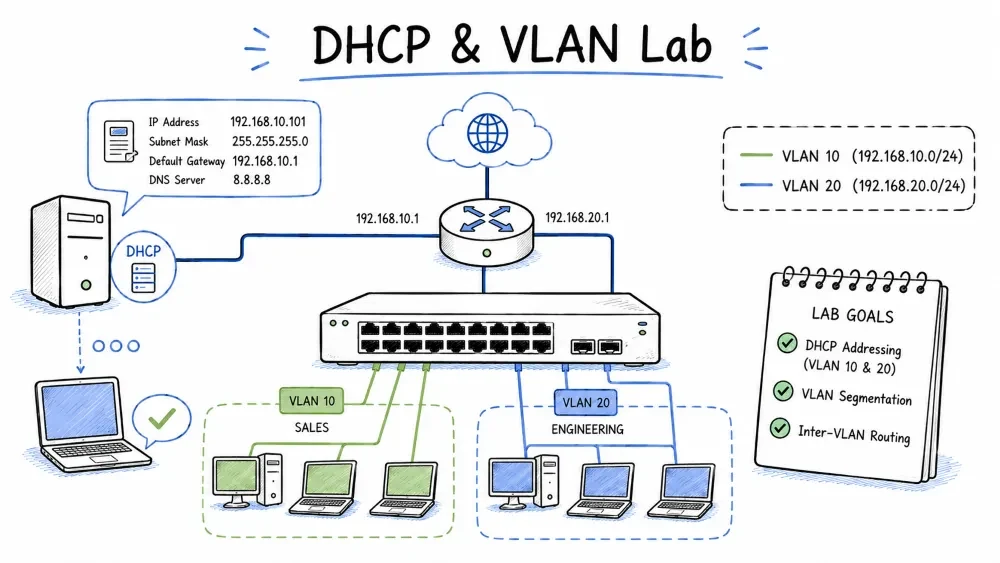
DHCP (Dynamic Host Configuration Protocol) is a network protocol that automatically assigns IP addresses, subnet masks, default gateways, DNS servers, and other network configuration parameters to devices when they connect to a network. Instead of manually configuring IP addresses on every device (which is time-consuming and error-prone), DHCP automates the entire process.
Understanding why DHCP is used helps you appreciate its role in network management. In any network larger than a handful of devices, manual IP configuration becomes impractical — each device needs a unique IP, correct subnet mask, and proper gateway. DHCP eliminates this administrative burden.
| Without DHCP | With DHCP |
|---|---|
| Manually configure each device's IP | Devices get IPs automatically |
| Risk of IP address conflicts (duplicate IPs) | DHCP server manages uniqueness |
| Devices need reconfiguration if network changes | Server update = all devices update at lease renewal |
| Time-consuming for large networks | Completely automated |
| Mobile devices require manual changes per location | IP assignment adapts to network |
DORA is the four-step process a DHCP client and server use to assign an IP address. Each step has a specific purpose — DISCOVER to find servers, OFFER to propose an IP, REQUEST to formally accept, and ACK to confirm the lease. Understanding DORA is essential for troubleshooting DHCP issues.
   PC (Client)                DHCP Server
      │                           │
      │  1. DHCP DISCOVER         │  (Broadcast — "Is there a DHCP server?")
      │──────────────────────────►│
      │                           │
      │  2. DHCP OFFER            │  (Unicast — "You can use 192.168.1.10")
      │◄──────────────────────────│
      │                           │
      │  3. DHCP REQUEST          │  (Broadcast — "I accept 192.168.1.10")
      │──────────────────────────►│
      │                           │
      │  4. DHCP ACK              │  (Unicast — "Confirmed. Lease granted.")
      │◄──────────────────────────│
      │                           │
| Step | Packet Type | Sender | Description |
|---|---|---|---|
| Discover | Broadcast | Client | "Is there a DHCP server out there? I need an IP address." |
| Offer | Unicast | Server | "Here is an available IP address: 192.168.1.10. Do you want it?" |
| Request | Broadcast | Client | "Yes, I want 192.168.1.10. Please assign it to me." |
| Ack | Unicast | Server | "Done. 192.168.1.10 is yours for the next 7 days." |
There are seven DHCP packet types that govern the complete lifecycle of an IP address lease, from initial assignment to renewal to release. Each packet type serves a specific purpose in the DHCP communication process.
| Packet | Sender | Purpose |
|---|---|---|
| DHCPDISCOVER | Client | Broadcast to locate available DHCP servers |
| DHCPOFFER | Server | Response to DISCOVER — offers an IP configuration |
| DHCPREQUEST | Client | Accepts the offered IP (or renews an existing lease) |
| DHCPACK | Server | Confirms the lease — client may now use the IP |
| DHCPNAK | Server | Rejects the request (e.g., subnet full, client moved to different network) |
| DHCPDECLINE | Client | The offered IP is already in use (client detected duplicate via ARP) |
| DHCPRELEASE | Client | Voluntarily releases the IP address (e.g., when shutting down) |
A DHCP lease has a finite lifetime (configurable in hours or days). The client goes through specific stages to maintain its lease — first trying to renew (when 50% of lease has passed), then rebinding (when 87.5% has passed), and finally restarting DORA if the lease expires.
Lease Timeline (7 days):

Day 0 ────────────────────── Day 3.5 ────────────────── Day 6.125 ──────── Day 7
│                                │                           │              │
Start                           T1 (50%)                   T2 (87.5%)    Expiry
│                                │                           │              │
Client gets IP         Client tries to RENEW       Client tries to     IP released
via DORA               with original server        REBIND (any server)
A Cisco router can function as a DHCP server for its directly connected networks. This is common in small-to-medium networks where a dedicated DHCP server is not available. The router's DHCP server assigns IP addresses from defined pools and manages leases automatically.
The DHCP pool configuration on a Cisco router defines the range of IP addresses to assign, the default gateway, DNS servers, and other options. Understanding each parameter is essential for proper DHCP setup.
Router(config)# ip dhcp pool <pool-name>
Router(dhcp-config)# network <network> <subnet-mask>
Router(dhcp-config)# default-router <gateway-ip>
Router(dhcp-config)# dns-server <dns-ip-1> <dns-ip-2>
Router(dhcp-config)# domain-name <domain>
Router(dhcp-config)# lease <days> <hours> <minutes>
| DHCP Pool Command | Description | Example |
|---|---|---|
network | The subnet to assign addresses from | 192.168.1.0 255.255.255.0 |
default-router | The gateway IP sent to clients | 192.168.1.1 |
dns-server | DNS server IP(s) for clients | 8.8.8.8 |
domain-name | DNS domain suffix | netgram.local |
lease | Lease duration | 7 0 0 (7 days) |
This example configures a router to provide DHCP services for the 192.168.1.0/24 network. It excludes static IPs from the pool, creates the pool, and enables the gateway interface.
! Step 1: Exclude static/reserved IPs from DHCP
! These IPs will NOT be assigned to DHCP clients
ip dhcp excluded-address 192.168.1.1 192.168.1.10

! Step 2: Create the DHCP pool and define parameters
ip dhcp pool LAN-POOL
 network 192.168.1.0 255.255.255.0
 default-router 192.168.1.1
 dns-server 8.8.8.8 8.8.4.4
 domain-name netgram.local
 lease 7
!

! Step 3: Configure the gateway interface (must be in the same subnet)
interface gigabitEthernet 0/0
 ip address 192.168.1.1 255.255.255.0
 no shutdown
A router interface can act as a DHCP client — typically used when the router connects to an ISP that assigns a public IP dynamically (like a cable or DSL modem). The interface requests an IP from the ISP's DHCP server.
interface gigabitEthernet 0/1
 description Connection to ISP (DHCP Client)
 ip address dhcp
 no shutdown
After configuring DHCP, you must verify that it is working correctly. These commands show you active leases, pool utilization, server statistics, and live DHCP events.
! View active DHCP leases (IP, MAC, lease expiration)
Router# show ip dhcp binding

! View pool statistics (assigned addresses, free addresses)
Router# show ip dhcp pool

! View server statistics (DISCOVERS, OFFERS, REQUESTS, ACKs)
Router# show ip dhcp server statistics

! View DHCP events in real-time (for troubleshooting)
Router# debug ip dhcp server events
show ip dhcp binding sample output:
Bindings from all pools not associated with VRF:
IP address      Client-ID/      Lease expiration        Type
                Hardware address/
                User name
192.168.1.11    0050.7966.6801   Jul 27 2026 12:00 PM   Automatic
192.168.1.12    0050.7966.6802   Jul 27 2026 12:00 PM   Automatic
192.168.1.13    0050.7966.6803   Jul 27 2026 12:15 PM   Automatic
In Packet Tracer, you can use a dedicated Server device as a DHCP server instead of using the router. A dedicated server provides more flexibility for managing multiple DHCP pools, and is more realistic in enterprise environments where DHCP runs on a dedicated server rather than the router.
This process configures the DHCP service on a Server device in Packet Tracer. The server is assigned a static IP and then configured with pool parameters through the graphical Services interface.
Add a Server to the Network:
Assign a Static IP to the Server:
192.168.1.10 (must be static and excluded from DHCP)255.255.255.0192.168.1.1Configure DHCP Service on the Server:
192.168.1.18.8.8.8192.168.1.100 (first assignable address)255.255.255.050Configure PC to Use DHCP:
Verify on the PC:
ipconfig and verify the PC received:
192.168.1.1)8.8.8.8)VLAN (Virtual Local Area Network) is a method of creating logically separated networks within the same physical switch. This section covers VLAN theory first, then applies it in a complete lab. You will build a network for a company with three departments, each in a separate VLAN, with a router providing inter-VLAN communication and DHCP services.
A VLAN (Virtual Local Area Network) is a logical grouping of devices within the same physical network that behave as if they are on their own separate network. VLANs allow you to segment a single physical switch into multiple isolated broadcast domains, improving security, reducing broadcast traffic, and simplifying network management.
Without VLANs, all devices on a switch share one broadcast domain — every broadcast frame reaches every device. With VLANs, broadcasts are contained within each VLAN, and devices in different VLANs cannot communicate directly without a router (Layer 3 device).
| Feature | Without VLANs | With VLANs |
|---|---|---|
| Broadcast Domain | One — broadcasts reach every device | Multiple — one per VLAN |
| Security | All devices can see each other's traffic | Traffic isolated between VLANs |
| Performance | Degraded by excessive broadcasts | Improved — broadcasts limited to VLAN |
| Flexibility | Physical re-cabling needed to move devices | Logical re-assignment only |
When a frame travels across a trunk, the switch inserts a 4-byte VLAN tag into the Ethernet frame header. This tag identifies which VLAN the frame belongs to. The receiving switch reads the tag and forwards the frame only to ports in that VLAN.
Original Ethernet Frame:
┌─────────┬───────────┬────────┐
│ Dest MAC│ Source MAC│ Payload│
└─────────┴───────────┴────────┘

802.1Q Tagged Frame:
┌─────────┬───────────┬──────┬─────────┬────────┐
│ Dest MAC│ Source MAC│ 802.1Q│  Type   │ Payload│
│         │           │ VLAN │        │        │
│         │           │ Tag  │        │        │
└─────────┴───────────┴──────┴─────────┴────────┘
Devices in different VLANs cannot communicate directly — they need a router or Layer 3 switch. One common method is Router-on-a-Stick, where a single router interface is divided into sub-interfaces, one per VLAN. Each sub-interface serves as the default gateway for its VLAN and routes traffic between VLANs.
Router
 ┌─────┴──────┐
 │ Gi0/0.10   │ 192.168.10.1 (Gateway for VLAN 10)
 │ Gi0/0.20   │ 192.168.20.1 (Gateway for VLAN 20)
 │ Gi0/0.30   │ 192.168.30.1 (Gateway for VLAN 30)
 └─────┬──────┘
       │ Trunk (802.1Q)
A company needs a network with three separate departments. Each department must be isolated at Layer 2 (no unnecessary broadcast traffic between departments), but they need to communicate at Layer 3 (to share resources like servers and printers). We use VLANs for isolation and a router for inter-VLAN communication.
| Department | VLAN ID | Network | Devices | Purpose |
|---|---|---|---|---|
| Sales | VLAN 10 | 192.168.10.0/24 | 4 PCs | Sales team works with CRM and customer data |
| Engineering | VLAN 20 | 192.168.20.0/24 | 4 PCs | Engineers need development tools |
| IT / Management | VLAN 30 | 192.168.30.0/24 | 2 PCs + Server | IT administration and company server |
                    ┌─────────────────┐
                    │   Router (RO)   │  (Router-on-a-Stick)
                    │  Gi0/0.10      │  - 192.168.10.1/24
                    │  Gi0/0.20      │  - 192.168.20.1/24
                    │  Gi0/0.30      │  - 192.168.30.1/24
                    └────────┬────────┘
                             │ Trunk (Gi0/1)
                             │ 802.1Q — VLANs 10, 20, 30
                    ┌────────┴────────┐
                    │  Switch (SW1)   │  (Layer 2 Switch)
                    │  Cisco 2960     │
                    └──┬──┬──┬──┬──┬──┘
          Fa0/1-4      │  │  │  │  │      Fa0/9-12
       ┌───────────────┘  │  │  │  └───────────────┐
       │            Fa0/5-8│  │Fa0/9-12            │
       │                  │  │                     │
  ┌────┴────┐      ┌─────┴──┴────┐      ┌─────────┴──┐
  │ Sales   │      │ Engineering │      │ IT Dept    │
  │ VLAN 10 │      │ VLAN 20     │      │ VLAN 30    │
  │ 4 PCs   │      │ 4 PCs       │      │ 2 PCs +    │
  │         │      │             │      │ Server     │
  └─────────┘      └─────────────┘      └────────────┘
Begin by placing all required devices on the Packet Tracer workspace. For this lab you need one router, one switch, PCs for each department, and a server.
| Device | Model | Quantity |
|---|---|---|
| Router | 4321 or 2911 | 1 |
| Switch | 2960 (24-port) | 1 |
| PC | PC-PT | 10 |
| Server | Server-PT | 1 |
Connect all devices with the correct cable types. The connection between the router and switch must be a trunk, while connections between the switch and end devices (PCs, server) are access ports.
| From | Port | To | Port | Cable Type |
|---|---|---|---|---|
| Router RO | Gi0/0 | Switch SW1 | Gi0/1 | Copper Straight-Through (Trunk) |
| PC-A1 (Sales) | Fa0 | SW1 | Fa0/1 | Copper Straight-Through |
| PC-A2 (Sales) | Fa0 | SW1 | Fa0/2 | Copper Straight-Through |
| PC-A3 (Sales) | Fa0 | SW1 | Fa0/3 | Copper Straight-Through |
| PC-A4 (Sales) | Fa0 | SW1 | Fa0/4 | Copper Straight-Through |
| PC-B1 (Engineering) | Fa0 | SW1 | Fa0/5 | Copper Straight-Through |
| PC-B2 (Engineering) | Fa0 | SW1 | Fa0/6 | Copper Straight-Through |
| PC-B3 (Engineering) | Fa0 | SW1 | Fa0/7 | Copper Straight-Through |
| PC-B4 (Engineering) | Fa0 | SW1 | Fa0/8 | Copper Straight-Through |
| PC-C1 (IT) | Fa0 | SW1 | Fa0/9 | Copper Straight-Through |
| PC-C2 (IT) | Fa0 | SW1 | Fa0/10 | Copper Straight-Through |
| Server | Fa0 | SW1 | Fa0/11 | Copper Straight-Through |
Log in to the switch CLI and create the three departmental VLANs plus a native VLAN. Each VLAN will later be assigned to specific switch ports and will have its own IP subnet.
Switch> enable
Switch# configure terminal
Switch(config)# hostname SW1

! Create VLANs for departments
SW1(config)# vlan 10
SW1(config-vlan)# name Sales
SW1(config-vlan)# exit

SW1(config)# vlan 20
SW1(config-vlan)# name Engineering
SW1(config-vlan)# exit

SW1(config)# vlan 30
SW1(config-vlan)# name IT
SW1(config-vlan)# exit

! Create a native VLAN (unused for data — security best practice)
SW1(config)# vlan 99
SW1(config-vlan)# name Native
SW1(config-vlan)# exit
Access ports carry traffic for a single VLAN. Each switch port connected to a PC or server must be configured as an access port and assigned to the correct VLAN based on which department the device belongs to.
! Ports Fa0/1-4 → VLAN 10 (Sales)
SW1(config)# interface range fastEthernet 0/1-4
SW1(config-if-range)# description Sales Department - VLAN 10
SW1(config-if-range)# switchport mode access
SW1(config-if-range)# switchport access vlan 10
SW1(config-if-range)# spanning-tree portfast
SW1(config-if-range)# no shutdown
SW1(config-if-range)# exit

! Ports Fa0/5-8 → VLAN 20 (Engineering)
SW1(config)# interface range fastEthernet 0/5-8
SW1(config-if-range)# description Engineering Department - VLAN 20
SW1(config-if-range)# switchport mode access
SW1(config-if-range)# switchport access vlan 20
SW1(config-if-range)# spanning-tree portfast
SW1(config-if-range)# no shutdown
SW1(config-if-range)# exit

! Ports Fa0/9-12 → VLAN 30 (IT)
SW1(config)# interface range fastEthernet 0/9-12
SW1(config-if-range)# description IT Department - VLAN 30
SW1(config-if-range)# switchport mode access
SW1(config-if-range)# switchport access vlan 30
SW1(config-if-range)# spanning-tree portfast
SW1(config-if-range)# no shutdown
SW1(config-if-range)# exit
The trunk port carries traffic for all VLANs between the switch and the router. Each frame on the trunk is tagged with a VLAN ID (802.1Q) so the router knows which VLAN the traffic belongs to. This allows the router to perform inter-VLAN routing.
SW1(config)# interface gigabitEthernet 0/1
SW1(config-if)# description Trunk to Router RO
SW1(config-if)# switchport mode trunk
SW1(config-if)# switchport trunk allowed vlan 10,20,30,99
SW1(config-if)# switchport trunk native vlan 99
SW1(config-if)# no shutdown
SW1(config-if)# end

! Save the configuration
SW1# copy running-config startup-config
Router-on-a-Stick is a network configuration method where a single physical router interface is divided into multiple logical sub-interfaces — one per VLAN. Each sub-interface is assigned a VLAN ID (using 802.1Q encapsulation) and an IP address that serves as the default gateway for devices in that VLAN.
Router> enable
Router# configure terminal
Router(config)# hostname RO

! Step 6a: Enable the physical interface (required before sub-interfaces work)
RO(config)# interface gigabitEthernet 0/0
RO(config-if)# no shutdown
RO(config-if)# exit

! Step 6b: Create sub-interface for VLAN 10 (Sales)
RO(config)# interface gigabitEthernet 0/0.10
RO(config-subif)# description Gateway for Sales VLAN 10
RO(config-subif)# encapsulation dot1Q 10
RO(config-subif)# ip address 192.168.10.1 255.255.255.0
RO(config-subif)# exit

! Step 6c: Create sub-interface for VLAN 20 (Engineering)
RO(config)# interface gigabitEthernet 0/0.20
RO(config-subif)# description Gateway for Engineering VLAN 20
RO(config-subif)# encapsulation dot1Q 20
RO(config-subif)# ip address 192.168.20.1 255.255.255.0
RO(config-subif)# exit

! Step 6d: Create sub-interface for VLAN 30 (IT)
RO(config)# interface gigabitEthernet 0/0.30
RO(config-subif)# description Gateway for IT VLAN 30
RO(config-subif)# encapsulation dot1Q 30
RO(config-subif)# ip address 192.168.30.1 255.255.255.0
RO(config-subif)# exit
Sub-Interface Configuration Explained:
| Component | Purpose | Example |
|---|---|---|
0/0.10 | Sub-interface number (often matches VLAN ID) | Gi0/0.10 → VLAN 10 |
encapsulation dot1Q 10 | Tags frames with VLAN 10 ID (802.1Q) | Essential for the router to identify the VLAN |
ip address | Sets the default gateway IP for this VLAN | 192.168.10.1 = gateway for VLAN 10 devices |
The router will now serve as the DHCP server for all three VLANs. Each VLAN gets its own DHCP pool, and the default gateway for each pool is the corresponding sub-interface IP. The router automatically knows which VLAN a DHCP request comes from based on which sub-interface received it.
! Step 7a: Exclude router sub-interface IPs from DHCP pools
! These are static and must not be assigned to clients
ip dhcp excluded-address 192.168.10.1
ip dhcp excluded-address 192.168.20.1
ip dhcp excluded-address 192.168.30.1

! Step 7b: DHCP Pool for VLAN 10 — Sales
ip dhcp pool SALES-POOL
 network 192.168.10.0 255.255.255.0
 default-router 192.168.10.1
 dns-server 8.8.8.8
 domain-name sales.netgram.local
 lease 7

! Step 7c: DHCP Pool for VLAN 20 — Engineering
ip dhcp pool ENGINEERING-POOL
 network 192.168.20.0 255.255.255.0
 default-router 192.168.20.1
 dns-server 8.8.8.8
 domain-name eng.netgram.local
 lease 7

! Step 7d: DHCP Pool for VLAN 30 — IT
ip dhcp pool IT-POOL
 network 192.168.30.0 255.255.255.0
 default-router 192.168.30.1
 dns-server 8.8.8.8
 domain-name it.netgram.local
 lease 7

! Step 7e: Save the configuration
RO# copy running-config startup-config
Each PC must be set to obtain its IP address automatically (DHCP) instead of using a static IP. The PC will use the DORA process to receive an IP from the router's DHCP server.
For each PC:
255.255.255.0192.168.10.1 for Sales)8.8.8.8Verification from a PC's Command Prompt:
C:\> ipconfig

FastEthernet0 Connection:(default port)
   Connection-specific DNS Suffix..: sales.netgram.local
   IP Address......................: 192.168.10.11
   Subnet Mask.....................: 255.255.255.0
   Default Gateway.................: 192.168.10.1
   DNS Server......................: 8.8.8.8
Expected IP Ranges per VLAN:
- Sales (VLAN 10): 192.168.10.11, .12, .13, .14
- Engineering (VLAN 20): 192.168.20.11, .12, .13, .14
- IT (VLAN 30): 192.168.30.11, .12 (PCs), .10 (Server)
Testing validates that the entire network is functioning correctly. We test Layer 2 connectivity (same VLAN), Layer 3 connectivity (between VLANs via router), and DHCP functionality (IP assignment).
Test 1: Within the Same VLAN (Layer 2 Switching)
| Test | Command | Expected Result |
|---|---|---|
| Sales PC-A1 → Sales PC-A2 | ping 192.168.10.12 | ✅ Success (same VLAN, same switch) |
| Engineering PC-B1 → PC-B2 | ping 192.168.20.12 | ✅ Success (same VLAN, same switch) |
| IT PC-C1 → IT PC-C2 | ping 192.168.30.12 | ✅ Success (same VLAN, same switch) |
Test 2: Between Different VLANs (Inter-VLAN Routing)
| Test | Command | Expected Result |
|---|---|---|
| Sales PC-A1 → Engineering PC-B1 | ping 192.168.20.11 | ✅ Success (router routes between VLANs) |
| Sales PC-A1 → IT Server | ping 192.168.30.10 | ✅ Success (router routes between VLANs) |
| Engineering PC-B1 → IT PC-C1 | ping 192.168.30.11 | ✅ Success (router routes between VLANs) |
Test 3: DHCP Verification
C:\> ipconfig /all

FastEthernet0 Connection:(default port)
   Connection-specific DNS Suffix..: sales.netgram.local
   Description.....................: FastEthernet0
   Physical Address................: 0050.7966.6801
   DHCP Enabled....................: Yes
   IP Address......................: 192.168.10.11
   Subnet Mask.....................: 255.255.255.0
   Default Gateway.................: 192.168.10.1
   DNS Server......................: 8.8.8.8
   Lease Obtained..................: Jul 20 2026 01:00:00 PM
   Lease Expires...................: Jul 27 2026 01:00:00 PM
In enterprise networks, DHCP is often handled by a dedicated server rather than the router. This approach provides more advanced DHCP features (like reservations, custom options, and centralized management). However, DHCP uses broadcasts (which do not cross VLANs), so we need a DHCP relay on the router to forward requests from each VLAN to the server.
Using Packet Tracer's Server device, create individual DHCP pools for each VLAN. The server must be reachable from all VLANs — it is placed in VLAN 30 (IT).
| Pool Name | Default Gateway | DNS Server | Start IP Address | Subnet Mask | Max Users |
|---|---|---|---|---|---|
| SalesPool | 192.168.10.1 | 8.8.8.8 | 192.168.10.100 | 255.255.255.0 | 50 |
| EngPool | 192.168.20.1 | 8.8.8.8 | 192.168.20.100 | 255.255.255.0 | 50 |
| ITPool | 192.168.30.1 | 8.8.8.8 | 192.168.30.100 | 255.255.255.0 | 50 |
DHCP relay (configured with ip helper-address) converts DHCP broadcast packets from clients into unicast packets sent to the DHCP server's IP address. Without this, clients in VLAN 10 and 20 cannot reach the DHCP server in VLAN 30 because broadcasts do not cross VLAN boundaries.
! Relay DHCP requests from VLAN 10 to the server at 192.168.30.10
RO(config)# interface gigabitEthernet 0/0.10
RO(config-subif)# ip helper-address 192.168.30.10

! Relay DHCP requests from VLAN 20 to the server at 192.168.30.10
RO(config)# interface gigabitEthernet 0/0.20
RO(config-subif)# ip helper-address 192.168.30.10
How
ip helper-addressworks: When a DHCP DISCOVER broadcast arrives on sub-interface Gi0/0.10, the router converts it to a unicast and sends it directly to192.168.30.10. The server's response is sent back, and the router delivers it to the original client.
What ip helper-address forwards (UDP broadcasts it relays):
| Protocol | Port |
|---|---|
| DHCP/BOOTP | 67/68 |
| DNS | 53 |
| TFTP | 69 |
| Time | 37 |
| NetBIOS | 137, 138 |
A systematic troubleshooting approach is essential when network communication fails. The OSI model provides a useful framework — start at Layer 1 (physical connectivity) and work up through Layer 2 (switching/VLANs) to Layer 3 (routing/IP).
When a PC cannot communicate, follow this layered approach to isolate the problem. Most networking issues are caused by simple misconfigurations at one of these layers.
| Symptom | Root Cause | How to Fix |
|---|---|---|
PC gets IP 169.254.x.x (APIPA) | DHCP server unreachable or no available addresses | Check DHCP server is on; check pool size; check ip helper-address for cross-VLAN |
| PC gets wrong subnet IP | Port in wrong VLAN | show vlan brief → verify port assignment |
| Duplicate IP detected | Two DHCP servers in the network | Disable extra DHCP servers; use DHCP snooping |
| DHCP requests not forwarded to server | Missing ip helper-address | Add ip helper-address <server-ip> on each VLAN sub-interface |
APIPA (Automatic Private IP Addressing): When a Windows PC fails to get a DHCP response, it auto-assigns an IP in the
169.254.x.xrange with mask255.255.0.0. This is definitive proof of a DHCP issue.
| Symptom | Root Cause | How to Fix |
|---|---|---|
| Devices in same VLAN can't ping each other | Port misconfigured or not in the same VLAN | show vlan brief → check port-to-VLAN mapping |
| Trunk not working | Allowed VLAN list missing or native VLAN mismatch | show interfaces trunk → verify allowed/native VLANs |
| Inter-VLAN ping fails | Router sub-interface not configured or trunk issue | show ip interface brief on router; check encapsulation |
| Slow connectivity | STP convergence delay (no PortFast) | Add spanning-tree portfast on access ports |
| Symptom | Root Cause | How to Fix |
|---|---|---|
| Can't ping gateway | Wrong default gateway configured | Verify ipconfig shows correct default gateway |
| Can ping gateway but not other VLANs | Routing issue on router or ACL blocks traffic | show ip route on router; check for ACLs |
| Inter-VLAN worked then stopped | Sub-interface went down or trunk issue | show ip interface brief → check if sub-interface is up/up |
On the Switch:
SW1# show vlan brief                ! Verify VLANs and port assignments
SW1# show interfaces trunk          ! Verify trunk status
SW1# show mac address-table         ! View MAC learning
SW1# show running-config            ! Review full configuration
On the Router:
RO# show ip interface brief         ! Verify sub-interfaces are up
RO# show ip route                   ! Verify routing table
RO# show ip dhcp binding            ! View DHCP leases
RO# show ip dhcp pool               ! View pool utilization
RO# show ip dhcp server statistics  ! View DHCP server stats
RO# debug ip dhcp server events     ! Watch DHCP messages (troubleshooting)
On a PC:
C:\> ipconfig /all                  ! Full IP configuration
C:\> ipconfig /renew                ! Request a new DHCP lease
C:\> ipconfig /release              ! Release current IP
C:\> ping <ip>                      ! Test connectivity
C:\> tracert <ip>                   ! Trace route to destination
This section provides the complete verified configuration for both the switch and router used in this lab. You can copy these configurations directly into Packet Tracer devices to replicate the lab setup.
hostname SW1
!
! Create VLANs
vlan 10
 name Sales
vlan 20
 name Engineering
vlan 30
 name IT
vlan 99
 name Native
!
! Access Ports — VLAN 10 (Sales)
interface range fastEthernet 0/1-4
 description Sales Department - VLAN 10
 switchport mode access
 switchport access vlan 10
 spanning-tree portfast
 spanning-tree bpduguard enable
 no shutdown
!
! Access Ports — VLAN 20 (Engineering)
interface range fastEthernet 0/5-8
 description Engineering Department - VLAN 20
 switchport mode access
 switchport access vlan 20
 spanning-tree portfast
 spanning-tree bpduguard enable
 no shutdown
!
! Access Ports — VLAN 30 (IT)
interface range fastEthernet 0/9-12
 description IT Department - VLAN 30
 switchport mode access
 switchport access vlan 30
 spanning-tree portfast
 spanning-tree bpduguard enable
 no shutdown
!
! Trunk Port to Router
interface gigabitEthernet 0/1
 description Trunk to Router RO
 switchport mode trunk
 switchport trunk allowed vlan 10,20,30,99
 switchport trunk native vlan 99
 no shutdown
!
end
hostname RO
!
! Enable the physical interface
interface gigabitEthernet 0/0
 no shutdown
!
! Sub-interface for VLAN 10 (Sales)
interface gigabitEthernet 0/0.10
 encapsulation dot1Q 10
 ip address 192.168.10.1 255.255.255.0
!
! Sub-interface for VLAN 20 (Engineering)
interface gigabitEthernet 0/0.20
 encapsulation dot1Q 20
 ip address 192.168.20.1 255.255.255.0
!
! Sub-interface for VLAN 30 (IT)
interface gigabitEthernet 0/0.30
 encapsulation dot1Q 30
 ip address 192.168.30.1 255.255.255.0
!
! Exclude gateway IPs from DHCP
ip dhcp excluded-address 192.168.10.1
ip dhcp excluded-address 192.168.20.1
ip dhcp excluded-address 192.168.30.1
!
! DHCP Pool for Sales (VLAN 10)
ip dhcp pool SALES-POOL
 network 192.168.10.0 255.255.255.0
 default-router 192.168.10.1
 dns-server 8.8.8.8
 domain-name sales.netgram.local
 lease 7
!
! DHCP Pool for Engineering (VLAN 20)
ip dhcp pool ENGINEERING-POOL
 network 192.168.20.0 255.255.255.0
 default-router 192.168.20.1
 dns-server 8.8.8.8
 domain-name eng.netgram.local
 lease 7
!
! DHCP Pool for IT (VLAN 30)
ip dhcp pool IT-POOL
 network 192.168.30.0 255.255.255.0
 default-router 192.168.30.1
 dns-server 8.8.8.8
 domain-name it.netgram.local
 lease 7
!
end
Expand the network by adding a second switch connected via trunk to the first switch. This tests your understanding of multi-switch VLAN propagation and trunk configuration.
Instructions:
Add an ISP router to simulate internet connectivity. This requires configuring NAT (Network Address Translation) and default routes — essential skills for connecting any internal network to the internet.
Instructions:
8.8.8.8/32) or connected subnet to simulate the internetip route 0.0.0.0 0.0.0.0 <isp-router-ip>8.8.8.8 (the simulated internet)Implement port security to prevent unauthorized devices from connecting to the network. This is a critical security measure in production networks.
Instructions: On Switch1, configure port security on all access ports:
interface range fastEthernet 0/1-12
 switchport port-security
 switchport port-security maximum 1
 switchport port-security mac-address sticky
 switchport port-security violation shutdown
Test:
show port-security interface fa0/1DHCP reservation (also called static DHCP) ensures a specific device always receives the same IP address from the DHCP server, based on its MAC address. This is useful for servers and printers that need a fixed IP but you still want to manage them through DHCP.
Instructions:
On the router, configure the Server to always receive 192.168.30.10:
! Find the server's MAC address first
! Then create a DHCP pool that assigns a fixed IP to that MAC
ip dhcp pool SERVER-RESERVATION
 host 192.168.30.10 255.255.255.0
 client-identifier 01xx.xxxx.xxxx.xx    ! Hex format of server's MAC
 default-router 192.168.30.1
 dns-server 8.8.8.8
Note: In Packet Tracer, DHCP reservation uses the
client-identifierwhich is the MAC address prefixed with01(for Ethernet).
This exercise tests your troubleshooting skills by introducing deliberate misconfigurations. You must identify and fix each issue using the diagnostic tools covered in this tutorial.
Scenario: A user in Sales (PC-A1) reports they cannot ping the Engineering server.
Possible issues to plant and fix:
show vlan briefshow ip interface briefshow interfaces trunkshow ip dhcp poolSteps to solution:
ping 192.168.20.11 — ❌ Failsipconfig — ✅ Has correct IP and gatewayshow vlan brief — ✅ Ports correctly assignedshow ip interface brief — ❌ Gi0/0.20 is administratively downinterface Gi0/0.20 → no shutdown — ✅ Fixed!Save your progress and earn XP for completing tutorials.
Technology
Cyber Security & Networking
Lesson group
CISCO Packet Tracer
Progress
100% complete