Preparing your learning space...
75% through CISCO Packet Tracer tutorials
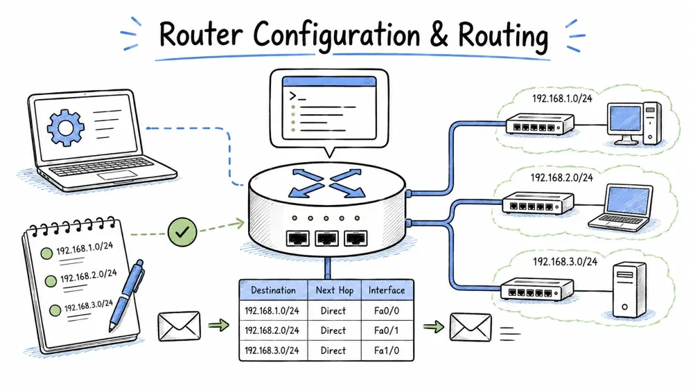
Routing is the process of forwarding data packets from one network to another. A router is a Layer 3 (Network Layer) device that uses IP addresses and a routing table to determine the best path for each packet. While switches forward frames within a single network (based on MAC addresses), routers enable communication between different networks — this is what makes the internet possible.
A router's primary job is to:
Path selection is the decision-making process a router uses to determine where to send each packet. This process happens for every single packet and is what enables traffic to find its way across complex networks with multiple possible paths.
   Packet arrives          Router checks routing        Packet forwarded
   ─────────────────►      table for dest. IP     ─────────────────►
                        ┌──────────────────────┐
                        │  192.168.2.0/24       │  → Forward via G0/1
                        │  via 10.0.0.2         │
                        │  [1/0]                │
                        │  "No match"           │  → Drop + ICMP
                        └──────────────────────┘
The routing table is a database stored in the router's memory that contains all known networks and the best path to reach each one. The table is built from directly connected networks, manually configured static routes, and dynamically learned routes from routing protocols.
Router# show ip route
Codes: C - connected, S - static, R - RIP, O - OSPF, D - EIGRP
       L - local

Gateway of last resort is not set

     10.0.0.0/30 is subnetted, 1 subnets
C       10.0.0.0 is directly connected, GigabitEthernet0/1
L       10.0.0.1/32 is directly connected, GigabitEthernet0/1
     192.168.1.0/24 is variably subnetted, 2 subnets
C       192.168.1.0/24 is directly connected, GigabitEthernet0/0
L       192.168.1.1/32 is directly connected, GigabitEthernet0/0
S       192.168.2.0/24 [1/0] via 10.0.0.2
Routing table sources indicate how a router learned about a particular route. The source code (the letter shown in the routing table) tells you whether the route is directly connected, manually entered, or learned through a dynamic protocol. This is important for troubleshooting — if a route is missing, you know where to look.
| Code | Source | How Learned | Reliability |
|---|---|---|---|
C | Connected | Directly attached network | Highest — always present if interface is up |
L | Local | Router's own IP address (IPv4) | Always present |
S | Static | Manually configured by administrator | High — you control it |
R | RIP | Routing Information Protocol (distance vector) | Low — convergences slowly |
O | OSPF | Open Shortest Path First (link state) | High — fast convergence |
D | EIGRP | Enhanced Interior Gateway Routing Protocol | High — very fast convergence |
B | BGP | Border Gateway Protocol (internet routing) | Very high — used for ISP networks |
Administrative Distance (AD) is a trustworthiness score that a router assigns to each route source. When a router learns about the same destination network from multiple routing protocols, it uses AD to decide which route to install in the routing table. Lower AD = more trustworthy. For example, a static route (AD 1) is preferred over an OSPF route (AD 110) to the same destination.
| Route Source | AD | Why This Value? |
|---|---|---|
| Connected Interface | 0 | Directly attached — most reliable |
| Static Route | 1 | Administrator-chosen — very reliable |
| EIGRP Summary Route | 5 | Cisco's protocol, summarized routes |
| External BGP (eBGP) | 20 | Routes from other autonomous systems |
| EIGRP (Internal) | 90 | Cisco's protocol, internal routes |
| OSPF | 110 | Industry standard, link-state protocol |
| RIP | 120 | Older distance vector, less reliable |
| Internal BGP (iBGP) | 200 | Routes within same autonomous system |
Example: If a router receives a route to
192.168.5.0/24via both OSPF (AD 110) and static configuration (AD 1), the static route wins because its AD is lower.
While AD compares trustworthiness between protocols, the metric compares path quality within the same protocol. Each routing protocol uses its own metric — for example, OSPF uses cost (based on bandwidth), while RIP uses hop count. When a protocol learns multiple paths to the same network, the path with the lowest metric is installed in the routing table.
| Protocol | Metric | What It Measures |
|---|---|---|
| RIP | Hop Count | Number of routers between source and destination (max 15) |
| OSPF | Cost | 10⁸ / Bandwidth (faster link = lower cost) |
| EIGRP | Composite | Bandwidth + Delay (+ Load + Reliability, optional) |
The router CLI is similar to the switch CLI but includes additional configuration modes specific to routing functions. Understanding these modes is essential as you will spend most of your configuration time navigating between them.
Router> enable
Router# configure terminal
Router(config)#
Router(config-if)#                     ! Interface configuration mode
Router(config-subif)#                  ! Sub-interface for VLAN routing (Router-on-a-Stick)
Router(config-router)#                 ! Routing protocol configuration (RIP/OSPF/EIGRP)
Router(config-line)#                   ! Console/vty line configuration
Initial router setup establishes basic identity and security parameters. Every router should have a unique hostname for identification, secure passwords for privileged access, and a legal warning banner.
Router> enable
Router# configure terminal
Router(config)# hostname Main-Router
Main-Router(config)# enable secret cisco123
Main-Router(config)# line console 0
Main-Router(config-line)# password cisco
Main-Router(config-line)# login
Main-Router(config-line)# exit
Main-Router(config)# line vty 0 4
Main-Router(config-line)# password cisco
Main-Router(config-line)# login
Main-Router(config-line)# exit
Main-Router(config)# banner motd #Unauthorized Access Prohibited - All activity is monitored#
| Command | Purpose |
|---|---|
hostname Main-Router | Sets the device name shown in the prompt |
enable secret cisco123 | Sets encrypted password for privileged EXEC access |
banner motd #...# | Creates a "Message of the Day" legal warning shown at login |
Router interfaces are the physical ports that connect the router to different networks. Each interface must be assigned an IP address and subnet mask that matches the network it connects to. Unlike switches, router interfaces are administratively down by default and must be explicitly enabled with no shutdown.
Main-Router(config)# interface gigabitEthernet 0/0
Main-Router(config-if)# ip address 192.168.1.1 255.255.255.0
Main-Router(config-if)# description Connection to Internal LAN - Sales Network
Main-Router(config-if)# no shutdown
Main-Router(config-if)# exit
Critical:
no shutdownenables the interface. Cisco routers default all interfaces to shutdown (administratively down). This is a safety feature — it prevents the router from connecting to a network before it is properly configured.
A loopback interface is a virtual interface on a router that is always up (as long as the router is running). Loopback interfaces are commonly used for:
Main-Router(config)# interface loopback 0
Main-Router(config-if)# ip address 1.1.1.1 255.255.255.255
Main-Router(config-if)# exit
Verifying interface status is a fundamental troubleshooting step. The show ip interface brief command provides a fast overview of all interfaces, their IP addresses, and their operational status. This should be your first command when debugging connectivity issues.
Main-Router# show ip interface brief
Output:
Interface              IP-Address      OK? Method Status                Protocol
GigabitEthernet0/0     192.168.1.1     YES manual up                    up
GigabitEthernet0/1     10.10.10.1      YES manual up                    up
Serial0/0/0            209.165.200.1   YES manual up                    up
Serial0/0/1            unassigned      YES unset  administratively down down
Reading the Output:
up = cable is connected and operational; administratively down = shutdown was appliedup = encapsulation/clocking is working; down = possible clocking or encapsulation mismatchStatic routing is the manual configuration of routes in a router's routing table. The administrator explicitly tells the router which path to use for each destination network. Static routing is simple, predictable, and uses no bandwidth for routing updates — but it does not adapt to network changes (link failures, etc.).
Static routing is best suited for:
The static route command tells the router: "To reach this destination network, send packets to this next-hop IP address or out this specific interface."
ip route <destination-network> <subnet-mask> <next-hop-ip | exit-interface>
| Component | Description |
|---|---|
destination-network | The network you want to reach (e.g., 192.168.2.0) |
subnet-mask | The subnet mask of the destination network (e.g., 255.255.255.0) |
next-hop-ip | The IP address of the next router that can forward to the destination |
exit-interface | The local interface to send the traffic out (alternative to next-hop) |
     192.168.1.0/24          10.0.0.0/30          192.168.2.0/24
  ┌────────────┐    Gi0/0   ┌──────────────┐  Gi0/0   ┌────────────┐
  │   LAN A    │◄──────────►│  Router-1    │◄─────────►│  Router-2  │◄──────│ LAN B │
  │  (PC-A)    │   .1       │ .1       .2  │  .1    .2 │            │
  └────────────┘            └──────────────┘           └────────────┘
For Router-1 to reach LAN B (which is not directly connected), we must configure a static route pointing to Router-2 as the next hop.
! Configure interfaces
interface gigabitEthernet 0/0
 ip address 192.168.1.1 255.255.255.0
 no shutdown

interface gigabitEthernet 0/1
 ip address 10.0.0.1 255.255.255.252
 no shutdown

! Static route to reach LAN B (192.168.2.0/24)
! Traffic destined for 192.168.2.x → send to Router-2 (10.0.0.2)
ip route 192.168.2.0 255.255.255.0 10.0.0.2
! Configure interfaces
interface gigabitEthernet 0/0
 ip address 192.168.2.1 255.255.255.0
 no shutdown

interface gigabitEthernet 0/1
 ip address 10.0.0.2 255.255.255.252
 no shutdown

! Static route to reach LAN A (192.168.1.0/24)
! Traffic destined for 192.168.1.x → send to Router-1 (10.0.0.1)
ip route 192.168.1.0 255.255.255.0 10.0.0.1
A default route (also called the "gateway of last resort" or "quad-zero route") matches any destination IP that doesn't have a more specific match in the routing table. It acts as a catch-all — "if you don't know where this network is, send it here." Default routes are essential for connecting internal networks to the internet.
! Send all unknown traffic to the ISP router at 203.0.113.1
Main-Router(config)# ip route 0.0.0.0 0.0.0.0 203.0.113.1
The
0.0.0.0 0.0.0.0notation means "any destination, any mask" — it matches all IP addresses.
Router-1# show ip route | include S
S       192.168.2.0/24 [1/0] via 10.0.0.2
S*      0.0.0.0/0 [1/0] via 203.0.113.1
S = Static route* = Candidate default route[1/0] = Administrative Distance (1) / Metric (0)via 10.0.0.2 = Forward to this next-hop IP addressDynamic routing protocols allow routers to automatically discover networks, share routing information with neighboring routers, and adapt to network changes (such as link failures or new connections) without manual intervention. Dynamic routing is essential in medium-to-large networks where static routing would be impractical to manage.
RIP (Routing Information Protocol) is one of the oldest dynamic routing protocols. It is a distance vector protocol that uses hop count as its metric. Each router that a packet crosses counts as one hop. RIP has a maximum hop count of 15 — any network 16 hops away is considered unreachable. RIP v2 supports VLSM and uses multicast updates.
| Attribute | Value |
|---|---|
| Type | Distance Vector |
| Metric | Hop count (max 15, 16 = unreachable) |
| Update Interval | Full routing table every 30 seconds |
| Convergence | Slow (minutes) |
| VLSM Support | RIP v1: ❌ No |
| Administrative Distance | 120 |
| Best For | Very small networks, educational labs |
Router-1(config)# router rip
Router-1(config-router)# version 2
Router-1(config-router)# network 192.168.1.0
Router-1(config-router)# network 10.0.0.0
Router-1(config-router)# no auto-summary
Router-1(config-router)# exit
Router-2(config)# router rip
Router-2(config-router)# version 2
Router-2(config-router)# network 192.168.2.0
Router-2(config-router)# network 10.0.0.0
Router-2(config-router)# no auto-summary
Router-2(config-router)# exit
RIP network statements use classful boundaries. RIP v1 automatically summarizes at classful boundaries;
no auto-summaryin RIPv2 allows subnets to be advertised individually.
| Command | Purpose |
|---|---|
show ip route rip | View only RIP-learned routes |
show ip protocols | Show all configured routing protocol parameters |
debug ip rip | Watch RIP updates in real-time (CPU intensive) |
show ip rip database | View the RIP topology database |
OSPF (Open Shortest Path First) is a link-state routing protocol that maintains a complete map of the network topology. Each OSPF router knows the state of every link in the network and calculates the shortest path to each destination using the SPF algorithm (Dijkstra's algorithm). OSPF is the most commonly used interior gateway protocol (IGP) in enterprise networks.
| Attribute | Value |
|---|---|
| Type | Link State |
| Metric | Cost = 10⁸ / Bandwidth (faster link = lower cost) |
| Update Type | Only changes (not full table) — very efficient |
| Convergence | Fast (seconds) |
| VLSM Support | ✅ Yes |
| Administrative Distance | 110 |
| Best For | Enterprise networks of all sizes |
| Term | Definition |
|---|---|
| Router ID (RID) | Unique identifier for each OSPF router (usually highest loopback IP) |
| Area | Logical grouping of routers to limit SPF calculations (Area 0 = backbone) |
| Link State Advertisement (LSA) | Packet containing link state information |
| Link State Database (LSDB) | Complete map of all LSAs in an area |
| Designated Router (DR) | Router that manages adjacencies on multi-access networks |
A single-area OSPF configuration places all routers in Area 0 (the backbone area). This is the simplest OSPF design and is appropriate for smaller networks (up to ~50 routers). All routers have a complete view of the entire network.
Router-1(config)# router ospf 1
Router-1(config-router)# router-id 1.1.1.1
Router-1(config-router)# network 192.168.1.0 0.0.0.255 area 0
Router-1(config-router)# network 10.0.0.0 0.0.0.3 area 0
Router-1(config-router)# exit
Router-2(config)# router ospf 1
Router-2(config-router)# router-id 2.2.2.2
Router-2(config-router)# network 192.168.2.0 0.0.0.255 area 0
Router-2(config-router)# network 10.0.0.0 0.0.0.3 area 0
Router-2(config-router)# exit
OSPF Process ID (
1) is locally significant — it only matters on the local router and does not need to match between routers. The Area ID (0) must match between routers for them to form an adjacency.
Wildcard Mask Explained:
The wildcard mask 0.0.0.255 is the inverse of the subnet mask 255.255.255.0. It tells OSPF to match all addresses in the 192.168.1.x range. A simpler modern alternative is to configure OSPF directly on the interface.
The interface-specific configuration method enables OSPF directly on each interface rather than using network statements. This is the modern, recommended approach as it is more precise and easier to read.
Router-1(config)# interface gigabitEthernet 0/0
Router-1(config-if)# ip ospf 1 area 0
Router-1(config-if)# exit
Router-1(config)# interface gigabitEthernet 0/1
Router-1(config-if)# ip ospf 1 area 0
OSPF cost determines path preference. By default, cost = 10⁸ / bandwidth. For example, a 100 Mbps FastEthernet link has a cost of 1 (10⁸ / 10⁸ = 1). You can manipulate cost to influence path selection — lower cost = preferred path.
! Option 1: Set interface cost manually (overrides automatic calculation)
Router-1(config)# interface gigabitEthernet 0/1
Router-1(config-if)# ip ospf cost 10

! Option 2: Change reference bandwidth (affects all OSPF interfaces)
! Set to 1000 (1 Gbps) so that 100 Mbps links have cost 10
Router-1(config-router)# auto-cost reference-bandwidth 1000
| Command | Purpose |
|---|---|
show ip route ospf | View only OSPF-learned routes |
show ip ospf neighbor | List neighboring OSPF routers and their states |
show ip ospf interface | Show OSPF parameters on each interface |
show ip ospf database | View the link-state database (LSDB) |
show ip protocols | Show all routing protocol parameters |
debug ip ospf adj | Watch OSPF adjacency formation (useful for troubleshooting) |
EIGRP (Enhanced Interior Gateway Routing Protocol) is Cisco's proprietary routing protocol (now partially open in 2013). It is an advanced distance vector protocol (sometimes called a "hybrid" protocol) that combines the best features of distance vector and link-state protocols. EIGRP uses the DUAL (Diffusing Update Algorithm) for fast convergence and loop-free path selection.
| Attribute | Value |
|---|---|
| Type | Advanced Distance Vector (Hybrid) |
| Metric | Composite formula: Bandwidth + Delay (default), optionally + Load + Reliability |
| Updates | Only changes (partial updates) — very efficient |
| Convergence | Very fast (sub-second with DUAL) |
| VLSM Support | ✅ Yes |
| Administrative Distance | Internal: 90 |
| Best For | Cisco-only enterprise networks |
| Term | Definition |
|---|---|
| Autonomous System (AS) | A group of routers running EIGRP with the same AS number |
| Successor | The primary route to a destination (best path) |
| Feasible Successor | A backup route that is loop-free (stored in topology table) |
| Feasible Distance (FD) | The total metric to reach a destination via the successor |
| Reported Distance (RD) | The metric advertised by a neighbor to reach a destination |
EIGRP configuration requires an Autonomous System (AS) number that must match between all routers in the EIGRP domain. The network command uses wildcard masks (like OSPF) and specifies which interfaces participate in EIGRP.
Router-1(config)# router eigrp 100
Router-1(config-router)# network 192.168.1.0 0.0.0.255
Router-1(config-router)# network 10.0.0.0 0.0.0.3
Router-1(config-router)# no auto-summary
Router-1(config-router)# exit
Router-2(config)# router eigrp 100
Router-2(config-router)# network 192.168.2.0 0.0.0.255
Router-2(config-router)# network 10.0.0.0 0.0.0.3
Router-2(config-router)# no auto-summary
Router-2(config-router)# exit
Autonomous System Number:
100must match between all routers. If Router-1 uses100and Router-2 uses200, they will not form an EIGRP neighbor relationship.
| Command | Purpose |
|---|---|
show ip route eigrp | View only EIGRP-learned routes |
show ip eigrp neighbors | List EIGRP neighbor routers |
show ip eigrp topology | View the EIGRP topology table (successors and feasible successors) |
show ip protocols | Show all routing protocol parameters |
debug eigrp packets | Watch EIGRP packet exchange |
Serial interfaces are used for Wide Area Network (WAN) connections between routers, typically over leased lines or frame relay. Serial connections require one side to be the DCE (Data Communications Equipment — typically the service provider side) and the other to be DTE (Data Terminal Equipment — typically the customer side). The DCE side provides the clock signal that synchronizes data transmission.
In Packet Tracer, when you connect two routers with a serial cable, one end has a small clock icon — that is the DCE end. The DCE end requires a clock rate command to set the line speed.
! On the DCE side (identified by clock icon in Packet Tracer)
Router-1(config)# interface serial 0/0/0
Router-1(config-if)# ip address 10.0.0.1 255.255.255.252
Router-1(config-if)# clock rate 128000    ! 128 Kbps line speed
Router-1(config-if)# no shutdown

! On the DTE side (no clock rate needed)
Router-2(config)# interface serial 0/0/0
Router-2(config-if)# ip address 10.0.0.2 255.255.255.252
Router-2(config-if)# no shutdown
Common Serial Cable Speeds:
| Clock Rate | Actual Speed |
|---|---|
| 56000 | 56 Kbps |
| 64000 | 64 Kbps |
| 128000 | 128 Kbps |
| 256000 | 256 Kbps |
| 512000 | 512 Kbps |
| 2000000 | 2 Mbps |
Network Address Translation (NAT) allows a router to translate private (internal) IP addresses to a public (external) IP address before sending traffic to the internet. This conserves public IPv4 addresses because many internal devices can share a single public IP address. NAT is one of the most common router configurations in real-world networks.
| Term | Definition | Example |
|---|---|---|
| Inside Local | Private IP of the internal device | 192.168.1.10 |
| Inside Global | Public IP assigned to the internal device after translation | 203.0.113.5 |
| Outside Global | Public IP of the destination on the internet | 8.8.8.8 |
NAT Overload (also called PAT — Port Address Translation) is the most common form of NAT. It allows many internal devices to share a single public IP address by using different source port numbers to distinguish between connections.
! Step 1: Define which addresses are "inside" (internal)
interface gigabitEthernet 0/0
 ip address 192.168.1.1 255.255.255.0
 ip nat inside

! Step 2: Define which interface is "outside" (external)
interface serial 0/0/0
 ip address 203.0.113.2 255.255.255.252
 ip nat outside

! Step 3: Create an ACL to match internal traffic to be translated
access-list 1 permit 192.168.1.0 0.0.0.255

! Step 4: Configure NAT overload (PAT) — many-to-one translation
ip nat inside source list 1 interface serial 0/0/0 overload
An Access Control List (ACL) is a sequential list of permit or deny statements that control traffic entering or leaving a router interface. ACLs are used for security (block unauthorized traffic), traffic filtering (control what types of traffic are allowed), and QoS marking (prioritize certain traffic types).
| Type | Filters On | Number Range | Placement |
|---|---|---|---|
| Standard ACL | Source IP address only | 1–99, 1300–1999 | Close to destination |
| Extended ACL | Source IP + Destination IP + Port + Protocol | 100–199, 2000–2699 | Close to source |
A standard ACL permits or denies traffic based only on the source IP address. Because it cannot filter on destination, standard ACLs should be placed as close to the destination as possible to avoid blocking legitimate traffic.
! Deny traffic from 192.168.1.0/24 (but allow all other traffic)
Router(config)# access-list 10 deny 192.168.1.0 0.0.0.255
Router(config)# access-list 10 permit any

! Apply the ACL to an interface (inbound or outbound)
Router(config)# interface gigabitEthernet 0/1
Router(config-if)# ip access-group 10 out
An extended ACL can filter on source IP, destination IP, protocol (TCP/UDP), and port number. This allows for very precise traffic control. Extended ACLs should be placed as close to the source as possible to filter traffic early.
! Block Telnet (port 23) from 192.168.1.0/24 to 192.168.2.0/24
! Allow everything else
Router(config)# access-list 100 deny tcp 192.168.1.0 0.0.0.255 192.168.2.0 0.0.0.255 eq 23
Router(config)# access-list 100 permit ip any any

! Apply to the incoming direction on the internal interface
Router(config)# interface gigabitEthernet 0/0
Router(config-if)# ip access-group 100 in
Important: Every ACL has an implicit deny any at the end. If traffic doesn't match any permit statement, it is denied by default. Always include a
permit anystatement if you want to allow traffic that doesn't match earlier rules.
This table compares the three dynamic routing protocols covered in this tutorial across key attributes. Use this as a quick reference when choosing a routing protocol for a network design scenario.
| Feature | RIP v2 | OSPF | EIGRP |
|---|---|---|---|
| Protocol Type | Distance Vector | Link State | Advanced Distance Vector |
| Metric | Hop count | Cost (bandwidth) | Bandwidth + Delay |
| Max Hop Count | 15 hops | Unlimited | 255 hops |
| Convergence Speed | Slow (minutes) | Fast (seconds) | Very fast (sub-second) |
| Routing Updates | Full table every 30s | Only changes (triggered) | Only changes (triggered) |
| VLSM / CIDR Support | ✅ Yes (v2) | ✅ Yes | ✅ Yes |
| CPU / Memory Usage | Very low | High (SPF calculations) | Medium (DUAL) |
| Cisco Proprietary? | No (Open standard) | No (RFC 2328/5340) | Yes (historically) |
| Network Size | Small (<15 routers) | Medium to Very Large | Medium to Large |
| Administrative Distance | 120 | 110 | 90 (internal) |
| Load Balancing | Equal-cost only | Equal-cost only (4 paths) | Unequal-cost (variance) |
This is a complete, production-style router configuration that incorporates all the concepts covered in this tutorial. Use it as a reference template for your own router configurations.
! ──── Main-Router (Cisco 4321) ────
!
hostname Main-Router
enable secret cisco123
!
! Loopback interface (used as OSPF Router ID)
interface loopback 0
 ip address 1.1.1.1 255.255.255.255
!
! Internal LAN interface
interface gigabitEthernet 0/0/0
 description LAN - Internal Network (192.168.1.0/24)
 ip address 192.168.1.1 255.255.255.0
 ip nat inside
 no shutdown
!
! WAN link to Branch Office
interface gigabitEthernet 0/0/1
 description WAN Link to Branch-Office (10.0.0.0/30)
 ip address 10.0.0.1 255.255.255.252
 no shutdown
!
! Serial WAN link to ISP
interface serial 0/1/0
 description WAN to ISP (203.0.113.0/30)
 ip address 203.0.113.2 255.255.255.252
 ip nat outside
 clock rate 128000
 no shutdown
!
! Default Route to ISP
ip route 0.0.0.0 0.0.0.0 203.0.113.1
!
! OSPF configuration
router ospf 1
 router-id 1.1.1.1
 network 192.168.1.0 0.0.0.255 area 0
 network 10.0.0.0 0.0.0.3 area 0
!
! NAT Overload (PAT) — share one public IP
ip nat inside source list NAT-ACL interface serial 0/1/0 overload
access-list 1 permit 192.168.1.0 0.0.0.255
!
! SSH Access
ip domain-name netgram.local
crypto key generate rsa modulus 1024
username admin secret cisco123
line vty 0 4
 login local
 transport input ssh
!
! Console Access
line console 0
 password cisco
 login
!
! Save configuration
copy running-config startup-config
Troubleshooting routing issues requires a systematic approach — starting with basic connectivity tests (ping) and moving to more specific diagnostic commands. These commands are the essential toolkit for diagnosing routing problems.
| Command | Purpose |
|---|---|
ping <ip> | Basic reachability test (ICMP Echo) |
traceroute <ip> | Shows the path a packet takes (list of routers between source and destination) |
extended ping | More advanced ping with configurable options (source IP, size, repeat count) |
| Command | Purpose |
|---|---|
show ip route | Display the full routing table |
show ip route <network> | Show route information for a specific network |
show ip interface brief | Quick status of all interfaces |
show interfaces <name> | Detailed interface statistics and errors |
show controllers serial 0/0/0 | Identify DCE/DTE side on serial links |
| Command | Purpose |
|---|---|
show ip protocols | Show all configured routing protocols |
show ip route rip | View RIP routes only |
debug ip rip | View RIP updates in real-time |
show ip route ospf | View OSPF routes only |
show ip ospf neighbor | List OSPF neighbors and adjacency state |
show ip ospf database | View OSPF link-state database |
show ip route eigrp | View EIGRP routes only |
show ip eigrp neighbors | List EIGRP neighbor routers |
show ip eigrp topology | View EIGRP topology table |
| Command | Purpose |
|---|---|
show ip nat translations | View active NAT translations |
show ip nat statistics | NAT hit/miss counters |
show access-lists | View ACL rules and match counters |
show ip interface <name> | Check if ACL is applied to an interface |
This lab requires you to build a three-router OSPF network with redundant paths. You will configure OSPF and observe how it dynamically chooses the best path and converges when a link fails.
     192.168.1.0/24        10.0.12.0/30        192.168.2.0/24
  PC-A ─── R1 ────────────────────── R2 ─── PC-B
                 \                  /
                  \  10.0.13.0/30  /  10.0.23.0/30
                   \              /
                    ──── R3 ─────
| Router | Interfaces | OSPF Area | Router ID |
|---|---|---|---|
| R1 | G0/0: 192.168.1.1/24, G0/1: 10.0.12.1/30, G0/2: 10.0.13.1/30 | Area 0 | 1.1.1.1 |
| R2 | G0/0: 192.168.2.1/24, G0/1: 10.0.12.2/30, G0/2: 10.0.23.2/30 | Area 0 | 2.2.2.2 |
| R3 | G0/1: 10.0.13.2/30, G0/2: 10.0.23.1/30 | Area 0 | 3.3.3.3 |
192.168.1.10/24, Gateway 192.168.1.1192.168.2.10/24, Gateway 192.168.2.1show ip route and ping| Test | Expected Result |
|---|---|
| PC-A pings PC-B | ✅ Success |
show ip route on R1 | ✅ Shows routes to 192.168.2.0/24 via OSPF |
show ip ospf neighbor on R1 | ✅ Shows R2 and R3 as neighbors (FULL state) |
traceroute 192.168.2.10 from PC-A | ✅ Shows path |
| Shutdown G0/1 on R1 → Test again | ✅ Traffic should reroute via R3 (after ~30 seconds) |
Save your progress and earn XP for completing tutorials.
Technology
Cyber Security & Networking
Lesson group
CISCO Packet Tracer
Progress
75% complete