Preparing your learning space...
100% through Routing & switching tutorials
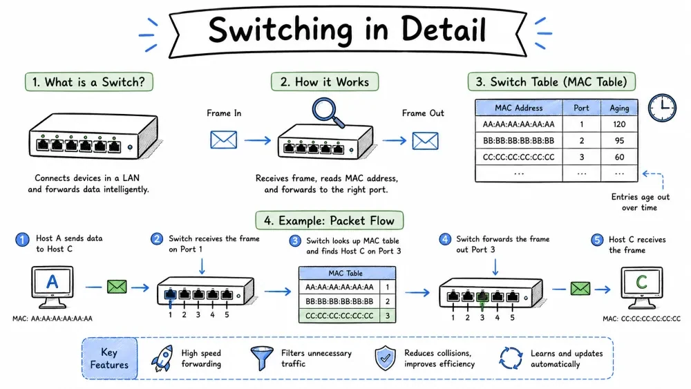
A Layer 2 device that connects multiple devices and forwards frames using MAC addresses.
A network switch is a Layer 2 (Data Link Layer) device that connects devices within the same network and forwards data based on MAC addresses.
+-----------------------------------------------------------+
|                       SWITCH                               |
|                                                          |
|  +------+  +------+  +------+  +------+  +------+       |
|  |Port 1|  |Port 2|  |Port 3|  |Port 4|  |Port 5|       |
|  +--+---+  +--+---+  +--+---+  +--+---+  +--+---+       |
|     |         |         |         |         |            |
|  +--+--+   +--+--+   +--+--+   +--+--+   +--+--+       |
|  | PC  |   | PC  |   | PC  |   | PC  |   | PC  |       |
|  |  A  |   |  B  |   |  C  |   |  D  |   |  E  |       |
|  +-----+   +-----+   +-----+   +-----+   +-----+       |
+-----------------------------------------------------------+
Comparing intelligence, forwarding behavior, and collision domains across devices.
| Feature | Hub | Switch | Router |
|---|---|---|---|
| Layer | Layer 1 (Physical) | Layer 2 (Data Link) | Layer 3 (Network) |
| Decision Basis | None | MAC Address | IP Address |
| Forwarding | Broadcast to all ports | Selective to target port | Based on routing table |
| Collision Domain | 1 (shared) | Per port | Per port |
| Broadcast Domain | 1 | 1 (per VLAN) | Per interface |
| Intelligence | None | MAC learning | Routing protocols |
Different switch categories based on features, management, and use cases.
| Type | Description | Use Case |
|---|---|---|
| Unmanaged | Plug-and-play, no configuration | Home/small office |
| Managed | Configurable, VLAN/STP/SNMP support | Enterprise networks |
| PoE | Power over Ethernet (powers devices via cable) | IP cameras, VoIP phones |
| Layer 3 | Can route between VLANs (has IP routing) | Campus networks |
| Stackable | Multiple switches operate as one | Data centers |
Access ports carry one VLAN; trunk ports carry multiple VLANs.
| Port Type | Function |
|---|---|
| Access Port | Carries traffic for ONE VLAN (connects to end devices) |
| Trunk Port | Carries traffic for MULTIPLE VLANs (connects to other switches) |
+--------------------------------------------------------------+
|                     SWITCHING PROCESS                        |
|                                                              |
|                      Frame Arrives                           |
|                           |                                  |
|                           v                                  |
|    +----------------------------------+                     |
|    |  1. LEARN                        |                     |
|    |     Source MAC -> Port, add to    |                     |
|    |     MAC Table                    |                     |
|    +--------------+-------------------+                     |
|                   v                                          |
|    +----------------------------------+                     |
|    |  2. LOOKUP                       |                     |
|    |     Destination MAC in MAC Table |                     |
|    +------+---------------+-----------+                     |
|           |               |                                  |
|           v               v                                  |
|    +-----------+    +--------------+                        |
|    | FOUND     |    | NOT FOUND     |                        |
|    | Forward   |    | Flood to all  |                        |
|    | to port   |    | ports (except |                        |
|    |           |    | source port)  |                        |
|    +-----------+    +--------------+                        |
+--------------------------------------------------------------+
Initial State: MAC Table is EMPTY

+----------+          +----------+          +----------+
|   PC A   |          |  SWITCH  |          |   PC B   |
| MAC: AA  |          |          |          | MAC: BB  |
| Port 1   |--------->|          |<---------| Port 2   |
+----------+          +----------+          +----------+

1. PC A sends frame to PC B
   +-------------------------------------------------+
   | Source MAC: AA | Dest MAC: BB | DATA           |
   +-------------------------------------------------+

2. Switch receives frame on Port 1
   -> LEARN: MAC AA -> Port 1  (added to MAC table)
   -> LOOKUP: MAC BB -> ?? (not in table)
   -> FLOOD: sends frame out ALL ports except Port 1
     (Port 2 receives it)

3. PC B sends reply to PC A
   +-------------------------------------------------+
   | Source MAC: BB | Dest MAC: AA | DATA           |
   +-------------------------------------------------+

4. Switch receives frame on Port 2
   -> LEARN: MAC BB -> Port 2  (added to MAC table)
   -> LOOKUP: MAC AA -> Port 1 (FOUND!)
   -> FORWARD: sends frame ONLY to Port 1

5. MAC Table is now populated:
   +------------+--------+
   |   MAC      | Port   |
   +------------+--------+
   | AA:AA:AA   |   1    |
   | BB:BB:BB   |   2    |
   +------------+--------+

Next time PC A sends to PC B -> forwards directly to Port 2
Different techniques a switch uses to forward frames, balancing speed vs error checking.
| Mode | How It Works | Latency | Error Checking |
|---|---|---|---|
| Store-and-Forward | Receives entire frame, checks CRC, then forwards | High | Full |
| Cut-Through | Reads dest MAC, forwards immediately (before full frame arrives) | Low | None |
| Fragment-Free | Reads first 64 bytes (checks for collisions), then forwards | Medium | Partial |
+------------------------------------------------------------+
|                    FRAME RECEPTION                          |
|                                                          |
|  +--+--+--+--+--+--+--+--+--+--+--+--+--+--+--+--+      |
|  |Pr|SF|  |  |  |  |  |  |  |  |  |  |  |  |  |CRC|     |
|  |e |D |  |DST MAC|SRC MAC|  DATA   |FCS|  |  |   |     |
|  +--+--+--+--+--+--+--+--+--+--+--+--+--+--+--+--+      |
|     ^            ^         ^                               |
|     |            |         |                               |
|  Cut-Through  Fragment  Store-and-Forward                  |
|  (reads dest)  (64 bytes)  (entire frame + CRC)           |
+------------------------------------------------------------+
Rules a switch follows to flood, forward, or drop a frame.
| Condition | Action |
|---|---|
| Destination MAC = Broadcast (FF:FF:FF:FF:FF:FF) | Flood to all ports (except source) |
| Destination MAC = Multicast | Flood to interested ports |
| Destination MAC found in table | Forward to specific port |
| Destination MAC NOT found | Flood to all ports (except source) |
| Source MAC = Dest MAC | Drop (invalid) |
The MAC table (also called CAM table -- Content Addressable Memory) is a database on a switch that maps MAC addresses to physical ports.
+--------------+----------+--------------+--------------+
|   MAC Address |  Port   |   VLAN       |   Type       |
+--------------+----------+--------------+--------------+
| AA:BB:CC:DD  |  Gi0/1  |   10         |   Dynamic    |
| EE:FF:00:11  |  Gi0/2  |   10         |   Dynamic    |
| 22:33:44:55  |  Gi0/3  |   20         |   Dynamic    |
| 66:77:88:99  |  Gi0/24 |   --         |   Static     |
+--------------+----------+--------------+--------------+
| Field | Description |
|---|---|
| MAC Address | The learned or configured MAC address |
| Port | Which switch port the device is connected to |
| VLAN | Which VLAN the device belongs to |
| Type | How the entry was learned (Dynamic/Static) |
How MAC addresses are learned — dynamically, statically, or via port security.
| Type | How Added | Description |
|---|---|---|
| Dynamic | Learned automatically | Expires after aging time (default 300s) |
| Static | Manually configured | Permanent entry |
| Secure | Port Security feature | Locked to specific MAC |
Dynamic MAC entries expire after a timeout period (default 300 seconds) to keep the table current.
+--------------------------------------------------+
|  Time     |  Event                               |
+-----------+--------------------------------------+
|  0s       | PC A sends frame -> MAC AA added      |
|  50s      | PC A sends another -> timer resets     |
|  100s     | PC A idle -- timer counting...         |
|  350s     | Still idle...                         |
|  400s     | Entry EXPIRED -> MAC AA removed        |
|  401s     | PC A sends frame -> MAC AA re-learned  |
+--------------------------------------------------+
Default aging time: 300 seconds (5 minutes) on most switches. Can be configured between 10 and 1,000,000 seconds.
Commands to inspect MAC address entries on Cisco switches and Linux.
show mac address-table
show mac address-table dynamic
show mac address-table static
bridge fdb show
Mac Address Table
Vlan    Mac Address       Type        Ports
----    -----------       ----        -----
  10    aabb.cc01.0101    DYNAMIC     Gi0/1
  10    aabb.cc02.0202    DYNAMIC     Gi0/2
  20    aabb.cc03.0303    DYNAMIC     Gi0/3
  20    aabb.cc04.0404    DYNAMIC     Gi0/4
Total Mac Addresses for this criterion: 4
A full MAC table forces flooding of unknown frames, reducing performance and enabling attacks.
Side-by-side comparison of Layer 2 switching and Layer 3 routing databases.
| Feature | MAC Table (Switch) | Routing Table (Router) |
|---|---|---|
| Layer | Layer 2 | Layer 3 |
| Key | MAC Address | IP Network |
| Learns from | Incoming frames | Routing protocols / config |
| Scope | Single broadcast domain | Entire internetwork |
| Timeout | Yes (aging timer) | No (unless dynamic route fails) |
A VLAN (Virtual LAN) is a logical subdivision of a physical network. It allows you to group devices together as if they were on the same physical network, even if they aren't.
+-----------------------------------------------------+
|  WITHOUT VLANS                                       |
|                                                       |
|  +-----------------+  +-----------------+           |
|  |  Sales Dept     |  |  Engineering    |           |
|  |  10 PCs         |  |  10 PCs         |           |
|  +--------+--------+  +--------+--------+           |
|           |                    |                      |
|           +----------+---------+                      |
|                      |                                |
|              +-------+--------+                       |
|              |    SWITCH      |   ALL IN ONE          |
|              |   (Flat LAN)   |   BROADCAST DOMAIN    |
|              +----------------+                       |
|                                                       |
|  X All traffic is visible to everyone                |
|  X No isolation between departments                  |
|  X Broadcasts reach ALL devices                      |
+-----------------------------------------------------+

+-----------------------------------------------------+
|  WITH VLANS                                          |
|                                                       |
|  +-----------------+  +-----------------+           |
|  |  VLAN 10        |  |  VLAN 20        |           |
|  |  Sales Dept     |  |  Engineering    |           |
|  |  10 PCs         |  |  10 PCs         |           |
|  +--------+--------+  +--------+--------+           |
|           |                    |                      |
|           +----------+---------+                      |
|                      |                                |
|              +-------+--------+                       |
|              |    SWITCH      |   TWO SEPARATE        |
|              |  VLAN 10 & 20  |   BROADCAST DOMAINS   |
|              +----------------+                       |
|                                                       |
|  Sales traffic stays in VLAN 10                      |
|  Engineering traffic stays in VLAN 20                |
|  Broadcasts isolated per VLAN                        |
|  ONE switch serving BOTH departments                 |
+-----------------------------------------------------+
VLANs improve security, reduce broadcast traffic, and add flexibility to network design.
| Benefit | Explanation |
|---|---|
| Security | Isolate sensitive departments (HR, Finance) |
| Broadcast Control | Reduce broadcast traffic (smaller broadcast domains) |
| Performance | Less unnecessary traffic reaching devices |
| Flexibility | Group users by function, not physical location |
| Simplified Management | Move a device by changing its VLAN, not its cable |
| Cost Savings | Fewer switches needed (one switch = many VLANs) |
VLAN IDs are divided into ranges — normal (1-1005) and extended (1006-4094).
| VLAN Range | Type | Purpose |
|---|---|---|
| 0, 4095 | Reserved | Cannot be used |
| 1 | Default | Default VLAN for all ports (cannot be deleted) |
| 2-1001 | Normal | Standard user VLANs |
| 1002-1005 | Reserved | Token Ring / FDDI (legacy) |
| 1006-4094 | Extended | Used in service provider networks |
! Create VLANs
vlan 10
 name SALES

vlan 20
 name ENGINEERING

! Assign access ports to VLANs
interface Gi0/1
 switchport mode access
 switchport access vlan 10

interface Gi0/2
 switchport mode access
 switchport access vlan 20
show vlan brief
show vlan id 10
show interfaces status
VLAN Name                             Status    Ports
---- -------------------------------- -------- ---------------------
1    default                          active    Gi0/3, Gi0/4, Gi0/5
10   SALES                            active    Gi0/1
20   ENGINEERING                      active    Gi0/2
1002 fddi-default                     act/unsup
1003 token-ring-default               act/unsup
1004 fddinet-default                  act/unsup
1005 trnet-default                    act/unsup
Devices in the same VLAN can communicate directly; different VLANs require a Layer 3 device.
+---------------------------------------------------------+
|                    VLAN 10 (SALES)                       |
|                                                          |
|   PC-A -------> PC-B    Same VLAN -> Direct             |
|   PC-A -------> PC-C    Same VLAN -> Direct             |
+---------------------------------------------------------+
+---------------------------------------------------------+
|                    VLAN 20 (ENGINEERING)                 |
|                                                          |
|   PC-D -------> PC-E    Same VLAN -> Direct             |
|   PC-D -------> PC-F    Same VLAN -> Direct             |
+---------------------------------------------------------+

VLAN 10 -------> VLAN 20    Different VLANs
    ^                            Need a Layer 3 device
    +----- Router / Layer 3 Switch ---- to route between them
VLANs are isolated by default. Devices in different VLANs cannot communicate unless traffic passes through a router or Layer 3 switch (VLAN routing / SVI).
Routing between different VLANs using a router or Layer 3 switch (router-on-a-stick or SVI).
+-----------------------------------------------------------+
|             INTER-VLAN ROUTING                             |
|                                                       |
|                    +----------+                       |
|                    |  Router  |  "Router-on-a-stick"  |
|                    |          |                       |
|                    |  .1      |                       |
|                    +----+-----+                       |
|                         | Trunk                        |
|                         |                              |
|  +----------------------+---------------------------+  |
|  |                   SWITCH                       |  |
|  |           VLAN 10 = Sales                      |  |
|  |           VLAN 20 = Engineering                |  |
|  +------+---------------------------+-------------+  |
|         |                           |                  |
|    +----+----+                 +----+----+           |
|    |  PC-A   |                 |  PC-B   |           |
|    | VLAN 10 |                 | VLAN 20 |           |
|    | 10.0.0.2|                 | 20.0.0.2|           |
|    +---------+                 +---------+           |
|                                                       |
|  PC-A -> PC-B (10.0.0.2 -> 20.0.0.2)                   |
|  1. PC-A sends to default gateway (10.0.0.1)          |
|  2. Router receives on sub-interface VLAN 10          |
|  3. Router checks routing table -> forwards via VLAN 20|
|  4. Switch delivers to PC-B                           |
+-----------------------------------------------------------+
Guidelines for planning and managing VLANs effectively in enterprise networks.
| Practice | Why |
|---|---|
| Use descriptive VLAN names | SALES not VLAN 10 -- easier to manage |
| Don't use VLAN 1 for user traffic | It's the default -- security risk |
| Create a separate management VLAN | Keep switch management isolated |
| Prune unused VLANs on trunks | Reduce unnecessary broadcast traffic |
| Use consistent VLAN numbering | Plan ahead (e.g., VLAN 10 = Sales everywhere) |
| Document VLAN to subnet mapping | Essential for troubleshooting |
Trunking allows a single link between switches to carry traffic for multiple VLANs. Without trunking, you'd need a separate physical link for each VLAN.
Trunk ports carry multiple VLANs on a single link; access ports carry only one VLAN.
|  WITHOUT TRUNKING                                         |
|                                                            |
|  Switch A                  Switch B                       |
|  +--------+               +--------+                      |
|  | VLAN 10|---------------| VLAN 10| 1 cable per VLAN     |
|  | VLAN 20|---------------| VLAN 20| Expensive / messy    |
|  +--------+               +--------+                      |
|                                                            |
|  WITH TRUNKING                                             |
|                                                            |
|  Switch A                  Switch B                       |
|  +--------+               +--------+                      |
|  | VLAN 10|               | VLAN 10|                       |
|  | VLAN 20|----TRUNK----->| VLAN 20| 1 cable carries ALL  |
|  | VLAN 30|   802.1Q      | VLAN 30| Economical           |
|  +--------+               +--------+                      |
A 4-byte VLAN tag is inserted into the Ethernet frame to identify which VLAN the traffic belongs to.
Each frame traveling on a trunk gets a VLAN tag inserted in the Ethernet header:
+---------------------------------------------------------------+
|                    STANDARD ETHERNET FRAME                     |
|                                                              |
|  +--------+--------+--------+----------+--------------+       |
|  |  Dest  |  Src   |  Type  |  DATA    |     FCS      |       |
|  |  MAC   |  MAC   | /Len   |          |   (CRC)      |       |
|  +--------+--------+--------+----------+--------------+       |
|                                                              |
|                   802.1Q TAGGED FRAME                        |
|                                                              |
|  +--------+--------+-----+--+--------+----------+------+     |
|  |  Dest  |  Src   |Tag|TP|  Type   |  DATA    |  FCS |     |
|  |  MAC   |  MAC   |    |ID| /Len    |          |      |     |
|  +--------+--------+-----+--+--------+----------+------+     |
|                        ^    ^                                |
|                   Tag Proto   VLAN ID (12 bits)              |
|                  0x8100       0-4095                         |
+---------------------------------------------------------------+
802.1Q Tag Fields:
0x8100 -- marks frame as taggedThe one VLAN on a trunk that travels untagged — both sides must agree on its ID.
The Native VLAN is the one VLAN that traverses a trunk without a tag. By default, it's VLAN 1.
+-----------------------------------------------------------+
|                     TRUNK LINK                             |
|                                                          |
|  Switch A <========================> Switch B          |
|                                                          |
|  Tagged:  VLAN 10, 20, 30 ---- tagged frames            |
|  Untagged: VLAN 1 (Native)  ---- untagged frames         |
|                                                          |
|  Both switches must agree on Native VLAN!               |
|  Mismatch = native VLAN mismatch error                   |
+-----------------------------------------------------------+
Security best practice: Change the native VLAN to an unused VLAN (never VLAN 1) to prevent "VLAN hopping" attacks.
! Configure trunk on an interface
interface Gi0/24
 switchport mode trunk
 switchport trunk native vlan 999
 switchport trunk allowed vlan 10,20,30
! Allow only specific VLANs
switchport trunk allowed vlan 10,20,30

! Add a VLAN to existing list
switchport trunk allowed vlan add 40

! Remove a VLAN
switchport trunk allowed vlan remove 20

! Allow all VLANs
switchport trunk allowed vlan all
show interfaces trunk
show interfaces Gi0/24 switchport
Port        Mode         Encapsulation  Status        Native vlan
Gi0/24      on           802.1q         trunking      999

Port        Vlans allowed on trunk
Gi0/24      10,20,30

Port        Vlans active and in the spanning tree
Gi0/24      10,20,30
Cisco proprietary protocol that automatically negotiates trunk links between switches.
Cisco switches support automatic trunk negotiation via DTP:
| Mode | Behavior |
|---|---|
| switchport mode access | Forces access mode (never trunks) |
| switchport mode dynamic desirable | Actively tries to form trunk with neighbor |
| switchport mode dynamic auto | Passive -- becomes trunk if neighbor asks |
| switchport mode trunk | Forces trunk mode regardless of neighbor |
Security best practice: Set unused ports to
switchport mode accessto prevent trunk negotiation with unauthorized devices.
STP (IEEE 802.1D) prevents bridging loops in networks with redundant paths. It creates a loop-free logical topology by blocking certain ports.
Redundant links without STP cause broadcast storms, MAC table instability, and duplicate frames.
Without STP, redundant links cause catastrophic problems:
+-----------------------------------------------------------+
|                  BRIDGING LOOP                             |
|                                                       |
|                   +------+                            |
|         +---------| SW-A |----------+                |
|         |         +------+          |                |
|         |           |               |                |
|         |           |               |                |
|         |     Redundant Links       |                |
|         |           |               |                |
|         |           v               |                |
|         |         +------+          |                |
|         +---------| SW-B |----------+                |
|                   +------+                            |
|                                                       |
|  Frame from PC-A -> Broadcast -> Loop!                |
|  SW-A sends to SW-B -> SW-B sends to SW-A -> infinity|
|  Broadcast storm -> Network collapse!                 |
+-----------------------------------------------------------+
| Problem | Description |
|---|---|
| Broadcast Storm | Broadcasts circulate infinitely, consuming all bandwidth |
| MAC Table Instability | Switch sees the same MAC on different ports repeatedly |
| Multiple Frame Copies | Destination receives duplicate frames (protocols break) |
STP places redundant links in a blocking state so there's only one active path:
+-----------------------------------------------------------+
|                   STP SOLUTION                             |
|                                                       |
|                     +------+                          |
|   ROOT BRIDGE ---->| SW-A |<-- Designated Port      |
|                     +---+--+                          |
|                         |  Forwarding                  |
|                         |                              |
|                    +----+----+                         |
|                    |         |                         |
|                    v         v                         |
|                  +------+   +------+                   |
|                  | SW-B |   | SW-C |                   |
|                  +--+---+   +---+---+                   |
|                     |          |                        |
|                 BLOCKED    Forwarding                   |
|                 (Alternate)                             |
|                                                       |
|  SW-B's port to SW-C is BLOCKED -> No loop             |
|  If primary link fails -> STP unblocks backup          |
|  Convergence: ~30-50 seconds (traditional STP)        |
+-----------------------------------------------------------+
Each switch port in STP takes a role — Root, Designated, Alternate, or Backup — to maintain a loop-free topology.
| Role | Description |
|---|---|
| Root Port (RP) | The best path to the Root Bridge (one per non-root switch) |
| Designated Port (DP) | The best port on a segment (one per segment) |
| Alternate Port (AP) | Backup to the Root Port (blocked) |
| Backup Port (BP) | Backup to a Designated Port (blocked, rare) |
Ports transition through Blocking, Listening, Learning, and Forwarding — taking ~50 seconds total.
DISABLED --> BLOCKING --> LISTENING --> LEARNING --> FORWARDING
   |                                                 |
   v                                                 v
Admin Down                                     Sending/Receiving
(No BPDUs)                                          Data

+-----------------------------------------------------------+
|  State      |  Forward Traffic?  |  Learn MACs?           |
+------------+--------------------+------------------------+
|  Disabled   |         No         |          No           |
|  Blocking   |         No         |          No           |
|  Listening  |         No         |          No           |
|  Learning   |         No         |          Yes          |
|  Forwarding |         Yes        |          Yes          |
+-----------------------------------------------------------+
Time in each state:
Three-step election: pick a Root Bridge, select Root Ports, then designate one port per segment.
STP uses a three-step election:
Step 1: Root Bridge Election
  "Who has the lowest Bridge ID?"
  Bridge ID = Priority (16 bits) + MAC Address (48 bits)

  Default Priority = 32768
  SW-A Priority 32768, MAC 0000.0A01.0101
  SW-B Priority 32768, MAC 0000.0A02.0202  <- Tie goes to lower MAC
  SW-C Priority 4096,  MAC 0000.0A03.0303  <- Lowest priority = ROOT!

  Root Bridge = SW-C (priority 4096)

Step 2: Root Port Selection (on non-root switches)
  Each non-root switch picks its best path to the Root:
  Criteria (in order):
    1. Lowest Root Path Cost
    2. Lowest Neighbor Bridge ID
    3. Lowest Neighbor Port ID

Step 3: Designated Port Selection (on each segment)
  On each link, one port is designated:
  Criteria (in order):
    1. Switch with lower Root Path Cost
    2. Switch with lower Bridge ID
Path cost values changed from the original 802.1D standard to the revised 802.1t to support higher link speeds.
| Speed | Original (802.1D) | Revised (802.1t) |
|---|---|---|
| 10 Mbps | 100 | 2,000,000 |
| 100 Mbps | 19 | 200,000 |
| 1 Gbps | 4 | 20,000 |
| 10 Gbps | 2 | 2,000 |
| 100 Gbps | 1 | 200 |
| 1 Tbps | -- | 20 |
Special frames exchanged every 2 seconds between switches to communicate STP information.
STP uses BPDUs to communicate between switches:
+-----------------------------------------------------------+
|                   BPDU FRAME                               |
|                                                          |
|  +--------------+----------------------------------+    |
|  | Protocol ID  | 0x0000                           |    |
|  | Version      | 0x00 (802.1D)                    |    |
|  | Message Type | 0x00 (Config BPDU)               |    |
|  | Flags        | TC, TCA                           |    |
|  | Root ID      | Priority + MAC of Root Bridge    |    |
|  | Root Path Cost| Cost from sender to Root         |    |
|  | Bridge ID    | Sender's own Priority + MAC       |    |
|  | Port ID      | Sender's Port number              |    |
|  | Max Age      | 20s (default)                     |    |
|  | Hello Time   | 2s (default)                      |    |
|  | Forward Delay| 15s (default)                     |    |
|  +--------------+----------------------------------+    |
|                                                          |
|  BPDUs are sent every 2 seconds (Hello Timer)            |
|  Multicast address: 01:80:C2:00:00:00                   |
+-----------------------------------------------------------+
Different versions of STP improve convergence time and add per-VLAN capabilities.
| Protocol | Standard | Convergence | Key Feature |
|---|---|---|---|
| STP | 802.1D | 30-50s | Original |
| RSTP | 802.1w | < 10s | Fast convergence |
| MSTP | 802.1s | < 10s | Multiple instances per VLAN group |
| PVST+ | Cisco | Varies | Per-VLAN STP (Cisco proprietary) |
| Rapid-PVST+ | Cisco | < 10s | Per-VLAN RSTP |
An improved STP that converges in under 10 seconds using a handshake mechanism instead of timers.
Key improvements over classical STP:
| STP (802.1D) | RSTP (802.1w) |
|---|---|
| 5 port states | 3 port states (Discarding, Learning, Forwarding) |
| Blocking / Disabled / Listening = all Discarding in RSTP | |
| Timer-based convergence | Proposal/Agreement handshake |
| 30-50 seconds | < 10 seconds |
| Port roles: Root, Designated, Alternate, Backup | Same + Backup refined |
                   +----------------+
                   |   EDGE PORT    |  <- Connected to end devices
                   | (Immediately   |     (no BPDUs expected)
                   |  Forwarding)   |
                   +----------------+

                   +----------------+
                   |  ROOT PORT     |  <- Best path to root
                   +----------------+

                   +----------------+
                   | DESIGNATED PORT|  <- Best port on segment
                   +----------------+

                   +----------------+
                   | ALTERNATE PORT |  <- Backup to root port
                   | (Discarding)   |
                   +----------------+

                   +----------------+
                   |  BACKUP PORT   |  <- Backup to designated
                   | (Discarding)   |
                   +----------------+
! Configure Bridge Priority (to influence root election)
spanning-tree vlan 10 priority 4096

! Enable PortFast (edge ports)
interface Gi0/1
 spanning-tree portfast

! Enable BPDU Guard (protect against rogue switches)
interface Gi0/1
 spanning-tree bpduguard enable

! Configure UplinkFast (for fast convergence on access switches)
spanning-tree uplinkfast

! Verify STP status
show spanning-tree
show spanning-tree vlan 10
show spanning-tree OutputVLAN0010
Spanning tree enabled protocol rstp
Root ID Priority 4096
Address aabb.cc03.0303
Cost 20000
Port 24 (GigabitEthernet0/24)
Hello Time 2 sec Max Age 20 sec Forward Delay 15 sec
Bridge ID Priority 32768 (priority 32768 sys-id-ext 10)
Address aabb.cc01.0101
Hello Time 2 sec Max Age 20 sec Forward Delay 15 sec
Aging Time 300 sec
Interface Role Sts Cost Prio.Nbr Type
-------- ---- --- ---- -------- ----
Gi0/1 Desg FWD 20000 128.1 P2p Edge
Gi0/2 Desg FWD 20000 128.2 P2p Edge
Gi0/24 Root FWD 20000 128.24 P2p
Gi0/23 Altn BLK 20000 128.23 P2p
Additional mechanisms to enhance STP stability and security against misconfiguration or attacks.
| Feature | Purpose | Configuration |
|---|---|---|
| PortFast | Bypass listening/learning for end devices | spanning-tree portfast |
| BPDU Guard | Shut down port if BPDU received (prevents rogue switches) | spanning-tree bpduguard enable |
| BPDU Filter | Suppress sending/receiving BPDUs on a port | spanning-tree bpdufilter enable |
| Root Guard | Prevent a port from becoming Root Port | spanning-tree guard root |
| Loop Guard | Prevent alternate ports from transitioning to forwarding if BPDUs stop | spanning-tree guard loop |
| UDLD | Detect unidirectional links (one-way traffic) | udld enable |
Common STP issues, their symptoms, and how to resolve them.
| Problem | Symptom | Solution |
|---|---|---|
| No root bridge elected | All ports blocking | Check BPDU transmission, link status |
| Wrong root bridge | Unexpected switch is root | Configure priority on intended root |
| Slow convergence | ~50 second delay | Use RSTP / Rapid-PVST+ |
| Duplicate frames | Intermittent connectivity issues | Check for loops, verify STP topology |
| BPDU Guard err-disable | Port is down (err-disabled) | shutdown then no shutdown on port |
You have a switch with 8 ports. The network is initially powered on, and the MAC table is empty. Devices are connected as follows:
+-----------------------------------------------------------+
|                         SWITCH                             |
|                                                          |
|  Port 1    Port 2    Port 3    Port 4    Port 5         |
|    |          |         |         |         |            |
|  PC-A      PC-B      PC-C      PC-D      PC-E           |
| MAC: AA   MAC: BB   MAC: CC   MAC: DD   MAC: EE        |
| IP: .10   IP: .20   IP: .30   IP: .40   IP: .50        |
|                                                          |
|     Port 6     Port 7      Port 8                       |
|       |          |           |                           |
|    Server-F   Printer-G   Laptop-H                      |
|    MAC: FF    MAC: GG     MAC: HH                        |
|    IP: .60    IP: .70     IP: .80                        |
+-----------------------------------------------------------+
| Step | Action |
|---|---|
| 1 | PC-A (Port 1) sends frame to PC-C (MAC: CC) |
| 2 | PC-C (Port 3) sends reply to PC-A (MAC: AA) |
| 3 | PC-B (Port 2) sends frame to Server-F (MAC: FF) |
| 4 | PC-D (Port 4) broadcasts ARP request "Who has 192.168.1.60?" |
| 5 | Laptop-H (Port 8) sends frame to PC-A (MAC: AA) |
| 6 | Server-F (Port 6) sends reply to PC-B (MAC: BB) |
After Step 1 -- PC-A -> PC-C (frame from AA to CC)
| MAC | Port | Notes |
|---|---|---|
| AA | 1 | Learned from source |
After Step 2 -- PC-C -> PC-A (reply from CC to AA)
| MAC | Port |
|---|---|
| AA | 1 |
| CC | 3 |
After Step 3 -- PC-B -> Server-F (frame from BB to FF)
| MAC | Port |
|---|---|
| AA | 1 |
| CC | 3 |
| BB | 2 |
After Step 4 -- PC-D broadcasts ARP (dest FF:FF:FF:FF:FF:FF)
| MAC | Port |
|---|---|
| AA | 1 |
| CC | 3 |
| BB | 2 |
| DD | 4 |
After Step 5 -- Laptop-H -> PC-A (frame from HH to AA)
| MAC | Port |
|---|---|
| AA | 1 |
| CC | 3 |
| BB | 2 |
| DD | 4 |
| HH | 8 |
After Step 6 -- Server-F -> PC-B (reply from FF to BB)
| MAC | Port |
|---|---|
| AA | 1 |
| CC | 3 |
| BB | 2 |
| DD | 4 |
| HH | 8 |
| FF | 6 |
Final MAC Table:
+------------+--------+
| MAC        | Port   |
+------------+--------+
| AA         |   1    |
| BB         |   2    |
| CC         |   3    |
| DD         |   4    |
| FF         |   6    |
| HH         |   8    |
| EE         |   (?)  | <- EE was never seen -- NOT in table
| GG         |   (?)  | <- GG was never seen -- NOT in table
+------------+--------+
Answer 5: PC-E (MAC EE) on Port 5 -- EE was never learned because PC-E never sent any frame during this sequence. The aging timer only applies to entries that exist. Since EE was never in the table, it doesn't matter that 10 minutes passed.
You are designing a network for a three-floor office building. Each floor has one switch, and all switches connect to a core switch in the server room. Redundant links exist for fault tolerance.
                              +----------------------+
                              |     CORE SWITCH       |
                              |      (SW-CORE)        |
                              +------+--------+-------+
                                     |        |
                +--------------------+        +--------------------+
                |                                                   |
           +----+----+                                        +----+----+
           | SW-F1   |                                        | SW-F2   |
           | Floor 1 |                                        | Floor 2 |
           +----+----+                                        +----+----+
                |                                                  |
                +----------------------+---------------------------+
                                       |
                                  +----+----+
                                  | SW-F3   |
                                  | Floor 3 |
                                  +---------+
| Department | Floor | VLAN ID | Subnet | PCs |
|---|---|---|---|---|
| Management | 1 | 10 | 10.0.10.0/24 | 10 |
| Engineering | 2 | 20 | 10.0.20.0/24 | 30 |
| Sales | 3 | 30 | 10.0.30.0/24 | 25 |
| IT Servers | Server Room | 99 | 10.0.99.0/24 | 5 |
Task A -- VLAN Configuration: Write the configuration commands for each switch to create the necessary VLANs. Which VLANs should exist on each switch?
Task B -- Trunking: Configure trunk ports between all switches (including SW-CORE). Which VLANs should be allowed on each trunk?
Task C -- STP Root Bridge:
aaaa.bbbb.cc01aaaa.bbbb.cc02 (priority set to 4096)aaaa.bbbb.cc03aaaa.bbbb.cc04Who becomes the root bridge? What command would you add to make SW-CORE the root bridge?
Task D -- Port Roles: Based on your root bridge selection in Task C:
Assume path costs: 1 Gbps = 4 (original 802.1D cost).
Task E -- Inter-VLAN Routing:
Task A -- VLAN Configuration
| Switch | Required VLANs |
|---|---|
| SW-CORE | 10, 20, 30, 99 |
| SW-F1 | 10, 99 |
| SW-F2 | 20, 99 |
| SW-F3 | 30, 99 |
SW-CORE Configuration:
vlan 10
 name MANAGEMENT
vlan 20
 name ENGINEERING
vlan 30
 name SALES
vlan 99
 name IT_SERVERS
SW-F1 Configuration:
vlan 10
 name MANAGEMENT
vlan 99
 name IT_SERVERS

interface Gi0/1
 switchport mode access
 switchport access vlan 10
!
interface Gi0/10
 switchport mode access
 switchport access vlan 99          ! Link to server room
Task B -- Trunking Configuration
SW-CORE trunk ports:
! Trunk to SW-F1
interface Gi0/1
 switchport mode trunk
 switchport trunk allowed vlan 10,99

! Trunk to SW-F2
interface Gi0/2
 switchport mode trunk
 switchport trunk allowed vlan 20,99

! Trunk to SW-F3
interface Gi0/3
 switchport mode trunk
 switchport trunk allowed vlan 30,99
SW-F1 trunk (to SW-CORE):
interface Gi0/24
 switchport mode trunk
 switchport trunk allowed vlan 10,99
SW-F2 to SW-F3 trunk (redundant link):
switchport trunk allowed vlan 99
Task C -- STP Root Bridge Election
| Switch | Priority | MAC | Lower MAC on tie? |
|---|---|---|---|
| SW-CORE | 32768 | aaaa.bbbb.cc01 | Lowest MAC of all -> would win with default settings |
| SW-F1 | 4096 | aaaa.bbbb.cc02 | Lowest priority -> SW-F1 WINS! |
| SW-F2 | 32768 | aaaa.bbbb.cc03 | |
| SW-F3 | 32768 | aaaa.bbbb.cc04 |
Root Bridge: SW-F1 (priority 4096 < 32768 of others)
This is likely not what we want -- the core switch should be root!
Fix: Set SW-CORE priority lower than 4096:
spanning-tree vlan 10 priority 0
spanning-tree vlan 20 priority 0
spanning-tree vlan 30 priority 0
spanning-tree vlan 99 priority 0
Or simpler: spanning-tree vlan 10,20,30,99 root primary
After fix, SW-CORE becomes root (priority 0 < 4096).
Task D -- Port Roles (after fixing root = SW-CORE)
Using the fixed topology (root = SW-CORE). Path cost: 1 Gbps = 4.
| Port | Path to Root | Cost | Role | State |
|---|---|---|---|---|
| SW-CORE -> SW-F1 | Direct | 0 | Designated | Forwarding |
| SW-CORE -> SW-F2 | Direct | 0 | Designated | Forwarding |
| SW-CORE -> SW-F3 | Direct | 0 | Designated | Forwarding |
| SW-F1 -> SW-CORE | Direct | 4 | Root Port | Forwarding |
| SW-F2 -> SW-CORE | Direct | 4 | Root Port | Forwarding |
| SW-F2 -> SW-F3 | Via SW-F3 -> SW-CORE = 4+4 = 8 | 8 | Alternate (Blocked) | Blocking |
| SW-F3 -> SW-CORE | Direct | 4 | Root Port | Forwarding |
| SW-F3 -> SW-F2 | Via SW-F2 -> SW-CORE = 4+4 = 8 | 8 | Alternate (Blocked) | Blocking |
Task E -- Inter-VLAN Routing
Option 1: Router-on-a-Stick (if using a dedicated router)
interface Gi0/0.10
 encapsulation dot1Q 10
 ip address 10.0.10.1 255.255.255.0

interface Gi0/0.20
 encapsulation dot1Q 20
 ip address 10.0.20.1 255.255.255.0

interface Gi0/0.30
 encapsulation dot1Q 30
 ip address 10.0.30.1 255.255.255.0

interface Gi0/0.99
 encapsulation dot1Q 99
 ip address 10.0.99.1 255.255.255.0
Option 2: Layer 3 Switch (SVI)
ip routing
interface vlan 10
 ip address 10.0.10.1 255.255.255.0
 no shutdown
interface vlan 20
 ip address 10.0.20.1 255.255.255.0
 no shutdown
interface vlan 30
 ip address 10.0.30.1 255.255.255.0
 no shutdown
interface vlan 99
 ip address 10.0.99.1 255.255.255.0
 no shutdown
PC Configuration:
| PC | IP Address | Subnet Mask | Default Gateway |
|---|---|---|---|
| Management PC (VLAN 10) | 10.0.10.x | 255.255.255.0 | 10.0.10.1 |
| Engineering PC (VLAN 20) | 10.0.20.x | 255.255.255.0 | 10.0.20.1 |
| Sales PC (VLAN 30) | 10.0.30.x | 255.255.255.0 | 10.0.30.1 |
| Server (VLAN 99) | 10.0.99.x | 255.255.255.0 | 10.0.99.1 |
The gateway IP for each VLAN is the router/L3 switch interface IP for that VLAN.
Save your progress and earn XP for completing tutorials.
Technology
Cyber Security & Networking
Lesson group
Routing & switching
Progress
100% complete