Preparing your learning space...
67% through Computer Networking tutorials
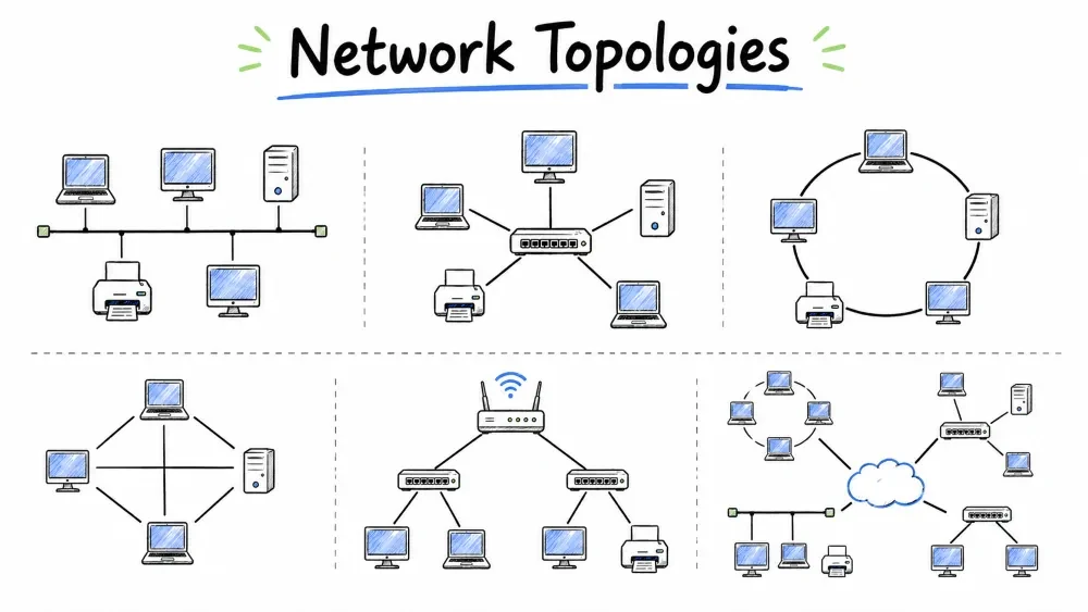
Network Topology is the physical or logical arrangement of devices (nodes) and the communication links between them in a computer network. It defines how devices are connected and how data flows from one device to another.
Network Topology refers to the arrangement of devices (nodes) and the connections (links) between them in a computer network.
         ┌─────────────────────────────────────┐
         │    "Topology = Layout of Network"    │
         └─────────────────────────────────────┘
| Type | Description |
|---|---|
| Physical Topology | How devices are physically connected (actual cable layout) |
| Logical Topology | How data flows between devices (may differ from physical) |
CCNA Note: CCNA focuses on both physical and logical topologies. In this tutorial, we cover physical topologies.
Bus Topology is a network topology in which all devices are connected to a single central cable, called the backbone or bus. Data travels along this cable in both directions, and each device checks whether the data is addressed to it.
In Bus Topology, all devices are connected to a single central cable called the backbone or bus.
        ┌──────┐     ┌──────┐     ┌──────┐     ┌──────┐
        │ PC 1 │     │ PC 2 │     │ PC 3 │     │ PC 4 │
        └──┬───┘     └──┬───┘     └──┬───┘     └──┬───┘
           │            │            │            │
           └────────────┼────────────┼────────────┘
                        │            │
           ═════════════╪════════════╪═══════════════  ← Bus / Backbone Cable
                        │            │
                     ┌──┴──┐      ┌──┴──┐
                     │ PC 5│      │ PC 6│
                     └─────┘      └─────┘

                    ◄──── Terminator ────►
                    (Both ends of cable)
| Aspect | Detail |
|---|---|
| Connection | All devices connect to a single coaxial cable |
| Terminators | Both ends of the cable have terminators (absorb signals) |
| Data Flow | Data travels in both directions along the bus |
| Protocol | Each device checks if data is addressed to it |
| Cable Type | Coaxial cable (like old TV cable) |
PC 1 sends data to PC 4:

   PC 1 ──►[DATA]──► PC 2 ──►[DATA]──► PC 3 ──►[DATA]──► PC 4 ✓
                                           (Ignored)         (Received)
                                    PC 5 ──►[DATA] ignored
                                    PC 6 ──►[DATA] ignored
Data travels along the bus. Every device sees the data, but only the intended recipient processes it.
| Advantage | Explanation |
|---|---|
| Simple setup | Easy to connect devices along one cable |
| Low cost | Requires less cable than star or mesh |
| Easy to extend | Just tap into the backbone cable |
| Good for small networks | Works well for 5–10 devices |
| Disadvantage | Explanation |
|---|---|
| Single point of failure | If the backbone cable breaks, the entire network goes down |
| Limited length | Cable length is limited (max ~185m for coaxial) |
| Performance drops | More devices = more collisions = slower network |
| Hard to troubleshoot | Finding a fault in the backbone is difficult |
| No security | All devices see all traffic |
| Terminators required | Missing terminators cause signal reflection and network failure |
Real-life use: Almost obsolete now. Was used in early Ethernet networks (10Base2, 10Base5).
Star Topology is a network topology in which all devices are connected to a central device (switch or hub). Each device has its own dedicated cable to the center, and all data must pass through the central device to reach its destination.
In Star Topology, all devices are connected to a central device (usually a switch or hub).
                          ┌─────────┐
                          │  PC 1   │
                          └────┬────┘
                               │
                    ┌──────────┼──────────┐
                    │          │          │
              ┌────┴────┐ ┌───┴────┐ ┌───┴────┐
              │  PC 2   │ │  PC 3  │ │  PC 4  │
              └─────────┘ └────────┘ └────────┘
                           │
                    ┌──────┴──────┐
                    │   SWITCH    │  ← Central Device
                    │   (HUB)     │
                    └──────┬──────┘
                           │
              ┌────────────┼────────────┐
              │            │            │
        ┌─────┴────┐ ┌────┴─────┐ ┌────┴─────┐
        │  PC 5    │ │  PC 6    │ │  PC 7    │
        └──────────┘ └──────────┘ └──────────┘
| Aspect | Detail |
|---|---|
| Connection | Each device has a dedicated cable to the central switch/hub |
| Central Device | Switch (intelligent) or Hub (dumb repeater) |
| Data Flow | All data goes through the central device |
| Cable Type | Twisted pair (Cat5e, Cat6) — RJ45 connectors |
PC 1 sends data to PC 4:

   PC 1 ──► SWITCH ──► PC 4 ✓
                │
                └──► Other ports — switch sends only to destination port
With a switch: data goes directly from source to destination port only. With a hub: data is broadcast to all ports (like bus topology).
| Advantage | Explanation |
|---|---|
| Easy to install | Simple cabling from each device to central switch |
| Easy to troubleshoot | Fault is easy to locate (check cable to central device) |
| Robust | If one cable fails, only that device is affected; rest of network works |
| Scalable | Add new devices easily by connecting to the switch |
| High performance | Dedicated bandwidth per device (with switch) |
| Centralized management | All traffic passes through central device — easy to monitor |
| Disadvantage | Explanation |
|---|---|
| Single point of failure | If the central switch fails, the entire network goes down |
| More cable required | Each device needs its own cable from the center |
| Cost | Switch/hub adds cost, especially for managed switches |
| Port limitation | Number of devices limited by available ports on the switch |
Real-life use: This is the most common topology used today. Almost all office and home networks use star topology (Ethernet switches).
Ring Topology is a network topology in which each device is connected to exactly two other devices, forming a closed loop or ring. Data travels around the ring in one direction (unidirectional) or both directions (bidirectional), and a token passing mechanism is used to control which device can transmit data at any given time.
In Ring Topology, each device is connected to exactly two other devices, forming a closed loop or ring.
                        ┌──────────┐
             ┌──────────│   PC 1   │──────────┐
             │          └──────────┘          │
             │                                │
      ┌──────┴──────┐                  ┌──────┴──────┐
      │    PC 6     │                  │    PC 2     │
      └──────┬──────┘                  └──────┬──────┘
             │                                │
             │          ┌──────────┐          │
             └──────────│   PC 3   │──────────┘
                        └──────────┘
                             │
                        ┌────┴────┐
                        │  PC 4   │
                        └─────────┘

   (Each device connected to 2 neighbors — forms a closed loop)
| Aspect | Detail |
|---|---|
| Connection | Each device connects to exactly two neighbors |
| Shape | Forms a closed loop / circle |
| Data Flow | Data travels in one direction (unidirectional) or both (bidirectional) |
| Token Passing | A special packet (token) controls who can transmit |
PC 1 wants to send to PC 4:

   Step 1: PC 1 waits for the empty token to arrive
   Step 2: PC 1 attaches data to the token and sends it
   Step 3: Token + data travels: PC 1 → PC 2 → PC 3 → PC 4
   Step 4: PC 4 receives the data and marks the token as "received"
   Step 5: Token continues back to PC 1, who releases the empty token
                          ┌─────────────────┐
                          │   Empty Token    │ ◄── Token circulates
                          │   (Free to use)  │     when idle
                          └─────────────────┘

   When a device wants to transmit:
        1. Grabs the token
        2. Attaches data to it
        3. Sends it around the ring
        4. Destination copies the data
        5. Token returns to sender
        6. Sender releases the empty token
| Advantage | Explanation |
|---|---|
| No collisions | Token passing ensures only one device transmits at a time |
| Predictable performance | Each device gets equal opportunity to transmit |
| Handles heavy load well | No collision-related slowdowns |
| Simple routing | Data travels in a fixed direction — no routing decisions needed |
| Disadvantage | Explanation |
|---|---|
| Single point of failure | If any one device or cable fails, the entire ring breaks |
| Difficult to troubleshoot | Finding the fault in a ring takes time |
| Adding/removing devices | Disrupts the network during changes |
| Slower than star | Data must pass through multiple devices before reaching destination |
| Obsolete technology | Rarely used in modern networks |
Real-life use: Was used in Token Ring networks (IBM). Now mostly replaced by star topology with Ethernet. Still used in some FDDI (Fiber Distributed Data Interface) networks for backbone.
Mesh Topology is a network topology in which devices are connected with many redundant interconnections between network nodes. In a full mesh, every device has a direct, dedicated point-to-point link to every other device. In a partial mesh, only critical devices have multiple connections.
In Mesh Topology, every device is connected to every other device in the network.
                ┌──────────┐
                │   PC 1   │
                └──┬───┬───┘
                   │   │
     ┌─────────────┤   ├──────────────┐
     │             │   │              │
┌────┴────┐   ┌───┴───┴───┐   ┌──────┴──────┐
│  PC 2   │◄─►│   PC 3    │◄─►│    PC 4     │
└────┬────┘   └───┬───┬───┘   └──────┬──────┘
     │            │   │              │
     └────────────┤   ├──────────────┘
                  │   │
             ┌────┴───┴────┐
             │    PC 5     │
             └─────────────┘

   Each device has a dedicated connection to every other device
                ┌──────────┐
                │   PC 1   │
                └──┬───┬───┘
                   │   │
                   │   │
              ┌────┘   └────┐
              │              │
        ┌─────┴────┐   ┌────┴──────┐
        │   PC 2   │   │   PC 3    │
        └─────┬────┘   └────┬──────┘
              │              │
              └──────────────┘

   Not all devices are connected — only critical ones
| Aspect | Full Mesh | Partial Mesh |
|---|---|---|
| Connections | Every device to every other | Only selected devices have redundant paths |
| Redundancy | Maximum | Partial |
| Cost | Very high | Moderate |
| Complexity | Very complex | Moderate |
PC 1 sends data to PC 4 in Full Mesh:

   Direct path:  PC 1 ────► PC 4  (direct link, no intermediate hops)
   Alternate:    PC 1 ──► PC 2 ──► PC 4  (if direct link fails)
                 PC 1 ──► PC 3 ──► PC 4  (another alternate)
If N = number of devices:

   Number of links required = N × (N - 1) / 2

   Example:
   N = 5  →  5 × 4 / 2 = 10 links
   N = 10 →  10 × 9 / 2 = 45 links
   N = 20 →  20 × 19 / 2 = 190 links
| Advantage | Explanation |
|---|---|
| Maximum reliability | Multiple redundant paths — no single point of failure |
| No traffic congestion | Dedicated point-to-point links |
| Fault tolerant | If one link fails, data uses alternate paths |
| High performance | No collisions, dedicated bandwidth |
| Secure | Only the two communicating devices see the traffic |
| Disadvantage | Explanation |
|---|---|
| Very high cost | Requires massive cabling and many ports |
| Complex setup | Every device needs N-1 NICs and ports |
| Difficult to maintain | Managing all connections is challenging |
| Cabling nightmare | Thousands of cables for large networks |
| Not practical for many devices | Cost and complexity grow exponentially |
Real-life use: Full mesh is used in WAN backbones (ISP core networks) and critical systems (military, banking). Partial mesh is used in some enterprise networks where redundancy is needed for critical servers.
Hybrid Topology is a network topology that combines two or more different types of topologies (such as star, bus, ring, or mesh) to form a larger, more flexible network. Most real-world enterprise networks use hybrid topology to meet diverse requirements.
Hybrid Topology is a combination of two or more different topologies. Most real-world networks are hybrid.
┌────────────────── HYBRID NETWORK ───────────────────┐
│                                                     │
│   ┌──── STAR 1 ────┐     ┌──── STAR 2 ────┐         │
│   │   ┌─────────┐  │     │   ┌─────────┐  │         │
│   │   │ Switch  │──┼─────┼───│ Switch  │  │         │
│   │   └──┬───┬──┘  │     │   └──┬───┬──┘  │         │
│   │   ┌──┘   └──┐  │     │   ┌──┘   └──┐  │         │
│   │   PC 1  PC 2   │     │   PC 3  PC 4   │         │
│   └────────────────┘     └────────────────┘         │
│                                                     │
│          ┌───────────── RING ──────────────┐        │
│          │  Router A ──── Router B         │        │
│          │      │              │           │        │
│          │      └──────────────┘           │        │
│          │      Router C                   │        │
│          └──────────────────────────────────┘       │
│                                                     │
└─────────────────────────────────────────────────────┘

   Star + Ring = Star-Ring Hybrid
| Aspect | Detail |
|---|---|
| Combination | Mix of bus, star, ring, mesh topologies |
| Design | Designed to meet specific organizational needs |
| Common examples | Star-bus, star-ring, tree topology (star-hierarchical) |
Hybrid Topologies:
├── Star-Bus:    Star networks connected via a bus backbone
├── Star-Ring:   Star networks connected in a ring
├── Tree:        Hierarchical star topology (like a tree structure)
└── Custom:      Any mix based on requirements
                         ┌──────────┐
                         │  Root    │
                         │  Switch  │
                         └────┬─────┘
                              │
          ┌───────────────────┼───────────────────┐
          │                   │                   │
     ┌────┴────┐        ┌────┴────┐        ┌────┴────┐
     │Switch A │        │Switch B │        │Switch C │
     └──┬───┬──┘        └──┬───┬──┘        └──┬───┬──┘
        │   │              │   │              │   │
       PC1  PC2           PC3  PC4           PC5  PC6
| Advantage | Explanation |
|---|---|
| Flexible | Can be designed to meet specific needs |
| Scalable | Easy to expand by adding more topology segments |
| Reliable | Fault in one segment doesn't affect the entire network |
| Optimized | Different segments can use the best topology for their need |
| Disadvantage | Explanation |
|---|---|
| Complex design | Requires careful planning |
| Higher cost | Multiple topology types require different equipment |
| Difficult to manage | Each topology segment may need different management strategies |
| Troubleshooting harder | Issues may span multiple topology types |
Real-life use: Every medium to large enterprise network is hybrid. For example, office floors use star topology, connected via a ring backbone between floors, with redundant mesh links to critical servers.
| Feature | Bus | Star | Ring | Mesh | Hybrid |
|---|---|---|---|---|---|
| Cost | Low | Medium | Medium | Very High | High |
| Cabling | Least | Moderate | Moderate | Maximum | Varies |
| Installation | Easy | Easy | Moderate | Very Hard | Complex |
| Troubleshooting | Hard | Easy | Moderate | Easy | Complex |
| Fault Tolerance | Poor | Good | Poor | Excellent | Good |
| Scalability | Poor | Good | Poor | Poor | Excellent |
| Performance | Poor (collisions) | Excellent | Good | Excellent | Good |
| Single Point of Failure | Backbone cable | Central switch | Any device | None | Depends |
| Common Use | Obsolete | Offices, Home | Legacy (Token Ring) | Backbone/Critical | Enterprise |
| CCNA Importance | Low | Highest | Low | Medium | Medium |
┌─────────────────────────────────────────────────────┐
│                 CHOOSING A TOPOLOGY                   │
├─────────────────────────────────────────────────────┤
│                                                      │
│  Consider these factors:                             │
│                                                      │
│  1. COST ──── How much budget do you have?           │
│  2. SCALE ─── How many devices?                      │
│  3. RELIABILITY ── Is downtime acceptable?           │
│  4. SPEED ──────── What performance is needed?       │
│  5. GROWTH ─────── Will the network expand?          │
│  6. MANAGEMENT ─── Who will maintain it?             │
│                                                      │
│  ┌────────────────────────────────────────────────┐  │
│  │  Small Home Network ──► Star (1 switch)        │  │
│  │  Small Office ────────► Star (1-2 switches)    │  │
│  │  School/College ──────► Star (multiple + tree) │  │
│  │  Enterprise ──────────► Hybrid (star + mesh)   │  │
│  │  ISP Core ────────────► Mesh (full or partial) │  │
│  │  Critical Systems ────► Mesh (redundancy)      │  │
│  └────────────────────────────────────────────────┘  │
│                                                      │
└─────────────────────────────────────────────────────┘
Full mesh links = N × (N - 1) / 2
A small office has 6 computers and 1 printer. They want to set up a network using Star Topology.
Your task: Draw the network diagram using ASCII characters (or describe in words) showing:
Read each scenario and select the most suitable topology (Bus, Star, Ring, Mesh, or Hybrid):
| # | Scenario | Your Choice |
|---|---|---|
| a | A hospital needs maximum reliability for its critical patient database — if one connection fails, another path must be available instantly | |
| b | A school wants to set up 30 computers in a lab with easy troubleshooting and the ability to add more computers later | |
| c | An enterprise has 3 departments on different floors — each floor uses star topology, and all floors are connected via a high-speed backbone | |
| d | In 1985, a company used a network where all computers connected to a single coaxial cable running through the office |
Save your progress and earn XP for completing tutorials.
Technology
Cyber Security & Networking
Lesson group
Computer Networking
Progress
67% complete